To add your own tiles, open the tile browser (menu Tile | Place | Tiles).
In the left menu of the tile browser, the database tree, you select .Custom Tiles. Rightclick and select Add Series.
Give a name and description and select OK. 

Rightclick (whitespace) and select Add Tile and load the tile picture. In the Tile Properties window insert the description, order number, type of tile, etc.

Press OK and start tiling!
Adding a non-rectangular tile
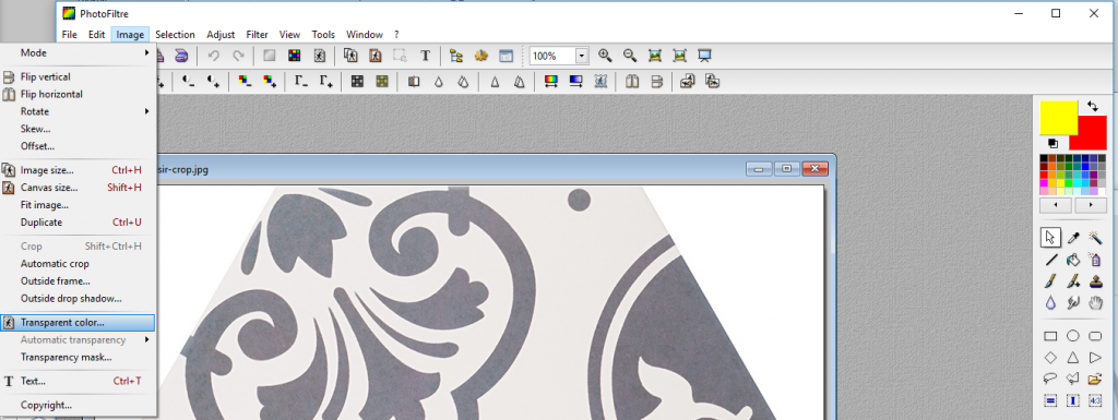
You may have to load a tile image that has a (white) background, for example, a hexagon tile. Before loading it in ViSoft, you will have to make the background transparent. This can be easily done with Photofiltre (install for free). Open the image in Photofiltre. Select Image > Transparent color…
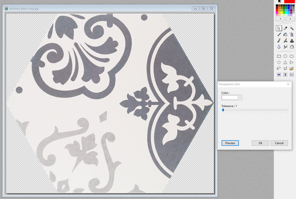
Select the white color. In this example the tolerance is set on 1, so no white from the tile itself is lost. Press preview to check the result. If the result is good, press OK. Save the image in .PNG (* .png) (to keep the transparent background).
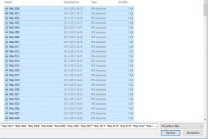
Open the Tile browser in ViSoft. Select .Custom Tiles and the serie – Rightclick and select Add Tile. Load the saved image and set the parameters.

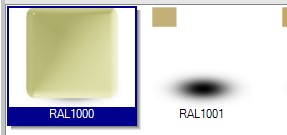
The tile is saved in your database. Select the tile preview and press OK to use it.
To make a module of the hexagon tile, go to menu TILE | PLACE | TILES and press Module assistant (bottom menu).
In the Module assistant set the mode on Manual and open the element parameters under More…
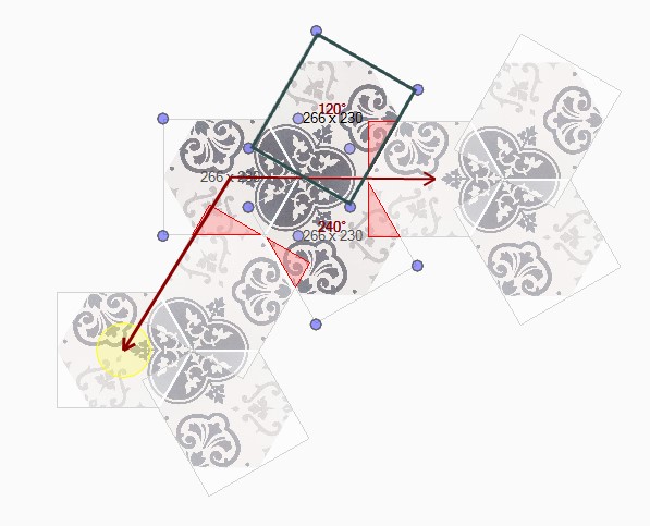
Drag the tile image to the working space. TIP: Rightclick while dragging to rotate the tile.

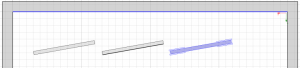
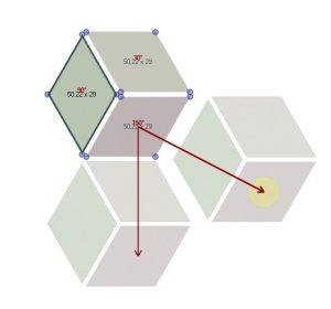
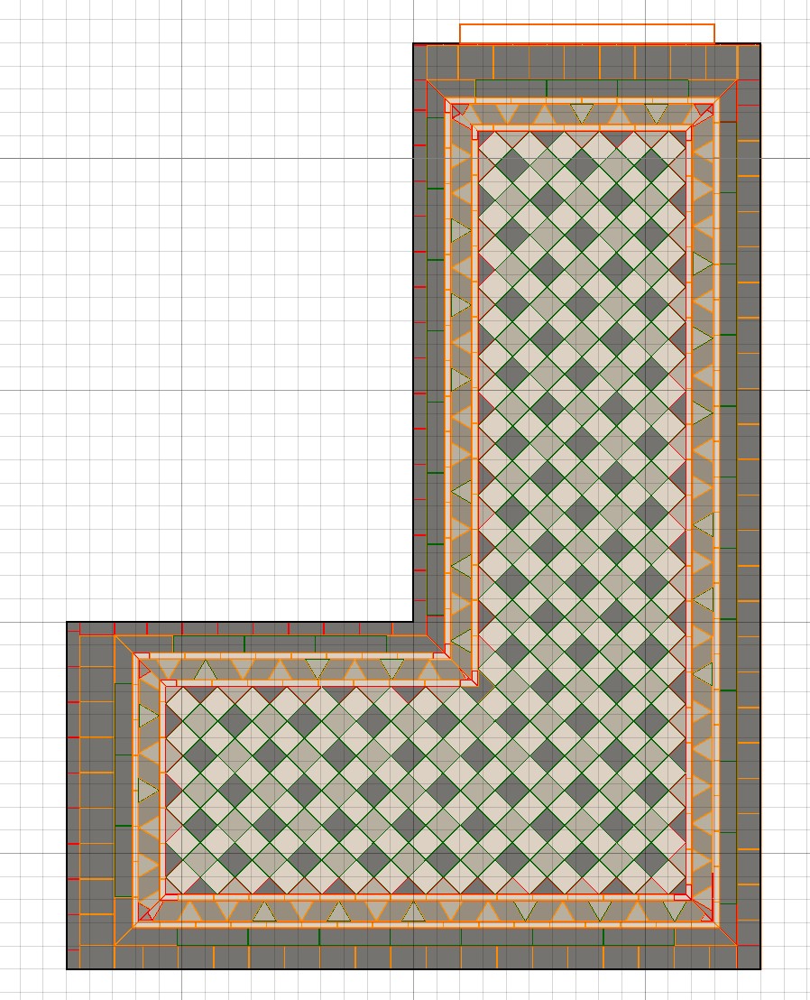
Drag two more tiles and connect them. To get the right angle, use the Element parameters | Free angle. Set the joint size on 2/3 mm. Use the red arrow (drag with yellow circle) to connect the module. In this example, red areas appear to signal overlap. This is not an issue however. TIP: Use the preview (bottom left), to check the end result and correct if needed.
 |
 |
 |
| Example module |
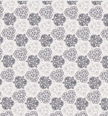
Module is nicely connected |
wrongly connected module |
Save the module as a tile pattern for future use (press save button upper menu). The tile pattern can be found under the tab Patterns in the tile browser.
Press OK to use the pattern in your project.
Import or export custom series
To import or export your custom made serie to other computers, right-click and select import or export to file. A .til format is created.


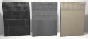
 Wall Board Assistant.

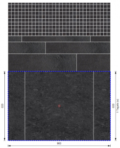
 to place the board in your project room. You can also choose to save the board. Use the button save…