You can add silicone in the Output – Part List – material. Click on the button Add Predefined Entries, find Silicone in the list and tick the box Add to part list. Select apply to close the window.
The needed amount of silicone is calculated automatically and added in the part list. ViSoft calculates for the floor the outside edge of the tiled area. For walls, it calculates the length between walls and outside edges of connected murals.
You can also add the needed wall and ceiling colors or stucco in the Parts List.
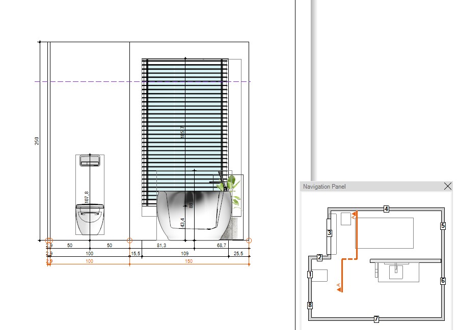
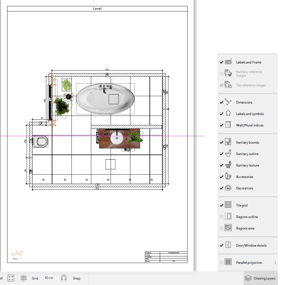
You can change the visibility of objects in the menu Output | Plan. In the ceiling plan when you open the navigation panel you can change the View Height.
In the following example, the view height is set on 160 cm. Objects that are above this height will then be displayed in the ceiling plan.
If you set the view height above the objects they will appear in the room plan.
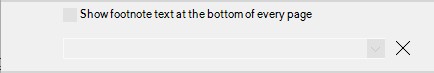
In the menu Output, you can add a footnote in the print settings. This footnote is one line and will be printed on each page at the bottom. If you want to use more text, use an image containing the text.
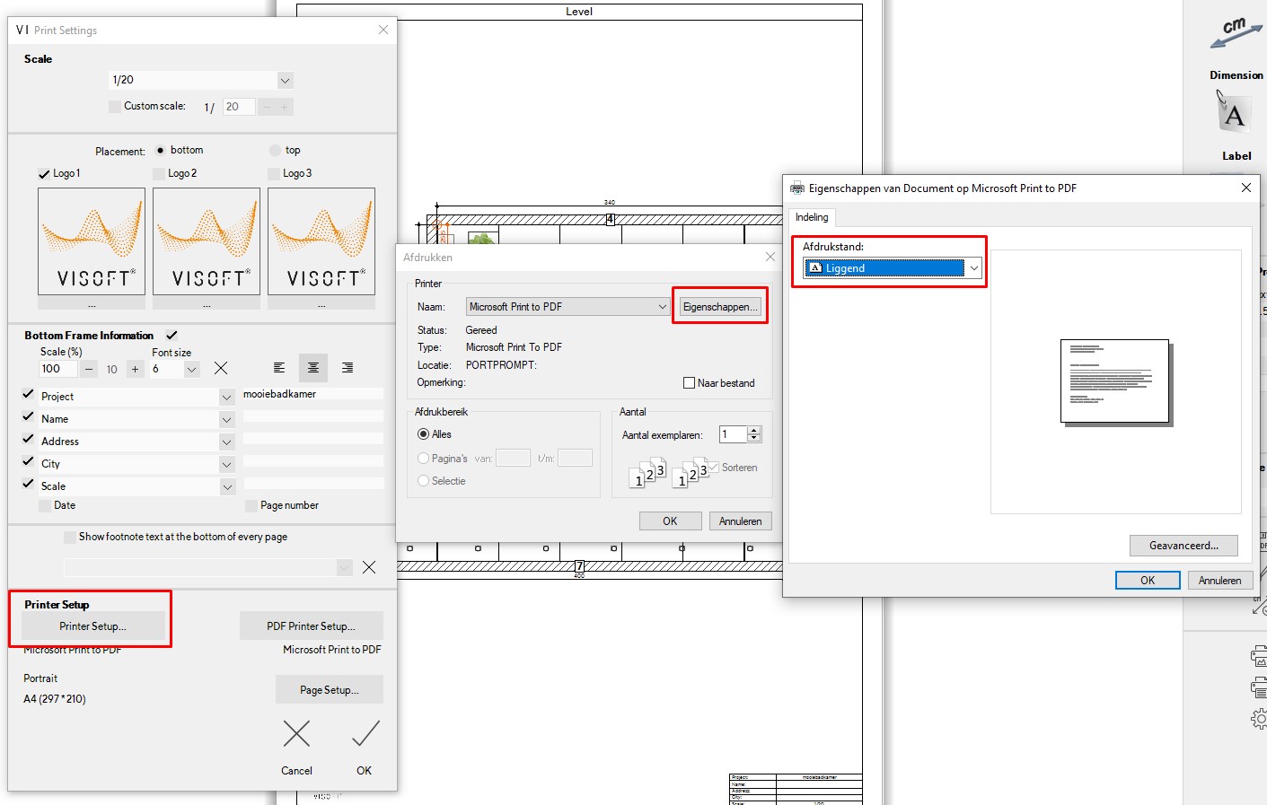
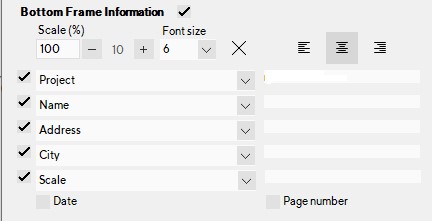
In the printer settings in the Output menu, you can add the Bottom Frame Information. You can change the scale and font size of the frame and check which lines you want in it. The information for the frame can be entered here as well.
If you want to change the name, address, City information you need to do this in File > customer info.
Attention: have Labels and frame turned on in the Drawing layers to have the Bottom frame information visible.
In the output select the Print Settings. In the menu select the button with 3 dots on it to add a logo, you can use a BMP, JPG or GIF file. Check the box above the logo on the position you want to use. The numbers accord to the left (1), middle (2) and right (3) of the page. You can also select if you want them on the top or bottom of the page.
It is also possible to add a logo with only text, for example, to have a disclaimer in the logos. For this use about a size of 850x115px.
Click on the Label button to add a text label. In the menu on the right in Text Label Properties you can change the text, font, layout, angle, and color of the text or frame.
After you made your label you can save it to the library. Right click on the label and select save to symbol library\labels. In the Symbol library, you can find the label folder on the left, the saved labels are in here.
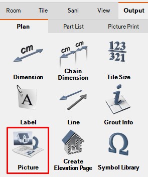
Using the button Picture in Output you open a windows folder to find the picture you want to add. After you placed a picture you can move, rotate and scale if you double click on it. You can also do this in the Symbol properties menu on the right.
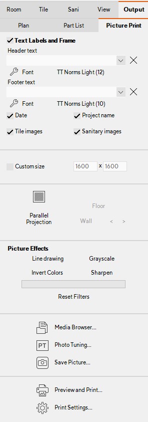
In the menu on the right, you can add Labels, a Frame, date, project name, tile images, and sanitary images. You can also choose a Custom size and Picture effects if you want.
When you have selected the wanted view and options to print. select the button Preview and Print. this shows you a preview of your print. Parallel Projection
With the parallel projection, you can make a 2D image instead of a 3D image. Click on Parallel Projection, and use the buttons and arrows to find the view you want. Saving a Picture
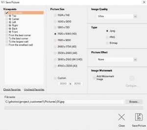
Multiple viewpoints can be saved as a JPG or BMP file. Select Save Picture and choose which viewpoints you want to save. You can set the Picture size, image quality, the file type, and a picture effect. At the bottom of the window, you choose the path and name of the picture.
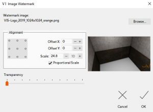
You can add your own watermark to the image by ticking the box; Add watermark image. once you ticked the box you can configure the watermark. select the image you want to use for example your logo in a .jpg or .png format. you can also choose the alignment, offset, and scale.
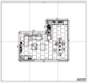
Sometimes it can be beneficial to print a large plan across multiple A4 pages. You can use the print preview to view how it is going to divide the print.
Set the scale of the plan in the Print Settings. select a custom scale, for example, 1/20.
The image below is an example of a plan that is divided across 6 pages. After printing this you can align them up using the guide marks.
In the Output menu, it is possible to add empty pages to create your own plan. Use the button Create Empty Page to get an empty page. You can add plans by dragging them in, or you can add labels and pictures from the right menu. Or, use the context menu to insert a plan page or picture.
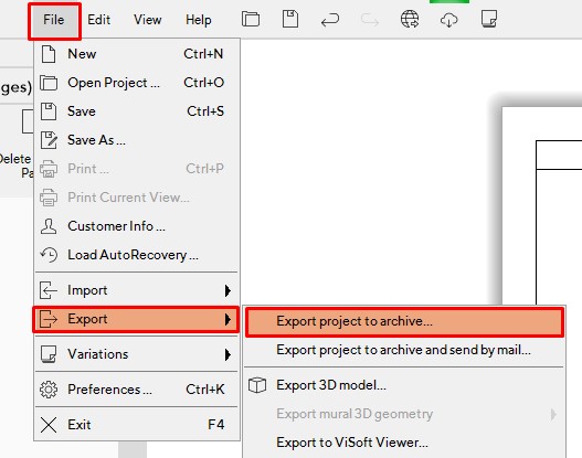
Read more about creating a zip file of a ViSoft project.
Use this function to export the projects that you made in ViSoft Premium. This can be useful if you want to transfer the project to a different pc with Visoft installed. Attention: this needs to be the same version as the one you made it with for example premium 2018. In the same way, import projects in ViSoft; File > import > import project from archive.
You can send the zip files via WeTransfer as they are most of the time too large for e-mail.
You can also use this function to create a back-up for your projects.
Exporting to CAD-software
Read more about exporting an image for editing in cad software.
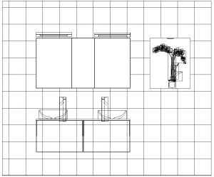
If you want you can export a plan or a different output view to for example Autocad to add plumbing measurements.
Below you find an example of a 2d image export opened in DoubleCad.
In the menu Output | Plan you find all the elevation pages of the room. Elevation pages are created automatically – one page for each wall.
The view in the elevation pages can be changed by moving the blue line in the navigation panel. It is also possible to remove or split the elevation with a right click.
You can add your own elevation with the button Create Elevation Page. Depending on how you draw the line the view will be above or below the line.
Right to left: Above the line.
Left to right: Below the line
Top to bottom: Right side
Bottom to top: Left side
Hit enter when you’re done or right click and select done or cancel.
A new Elevation page is created. You can rename the page by right clicking on the page name and select rename.
It is possible to add your own Impacts to the library. You need two images for ViSoft to work with. The first image has to be a JPEG in the correct size ( 128×128 pixels) the second the same image in png ( 24 x 24 pixels ). The images have to be placed in the following path.
Sanitary impacts in: C:\ViSoftCreative\ Data \ Impacts\ Electrical
For ViSoft without dongle: C:\ Program Files \ ViSoft \ ViSoftPremium\Data\ Impacts \ Electrical
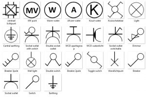
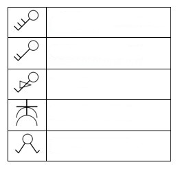
There are different possibilities to add a legend to the plans of your project. In the Output | Plan menu you can add a text label with the explanation and symbols as examples.
You can also create a legend in a program such as Word or Excell. if you then take a screenshot of that legend, you can add it as an image to your plan.
If you are missing symbols you can add them yourself in;
C:\ViSoftCreative\ UserData\Output\Symbols\
Online installation (without dongle) C:\ProgramData\ViSoft\ViSoftPremium\
Sanitary impacts are in: C:\ViSoftCreative\ Data \ Impacts\ Electrical
Online installation: C:\ Program Files \ ViSoft \ ViSoftPremium\Data\ Impacts \ Electrical
You can use the following image to create a legend of your own.
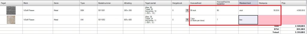
With this function, ViSoft calculates the number of boxes needed for the room. The price will then be shown in the part list of the Output.
For a correct price calculation, you will need to enter the price per box in the properties of the tile. You can find it in the: more parameters.
After the information is filled in, you can set the unit in the part list to box. The amount shows how many boxes you need and how many tiles are in the box. Next to the amount is the amount of boxes to order.
The price is calculated after the price per box, piece or m² is put in.
This function automatically calculates how many cut tiles can be reused in the project. It also shows ways how to cut the tiles for reuse.
To determine the reuse of tiles, turn on Tile offcut reusage layer. The tiles that are cut in half, are marked with the same color and index number (bold = the larger part, italics for the smaller cut).
In menu Output | Part list you open the part list for tiles. The calculations for tile optimization are shown here. Click on the question mark under reused tiles to open the Tile Offcuts window. Choose the way tiles can be reused, this depends on the structure.
The texture of decorative tiles can’t be reused.
The tile texture can only be rotated horizontally or vertically.
The tile can be reused and rotated 180 degrees (tiles with the same repeating texture in one direction).
The tile structure can be rotated both horizontally and vertically. The tile can be reused and vice versa (tiles with the same repetitive texture in all directions)
This window shows the tile cut plan. The black indicates the cutting loss.
In menu Output | Part list |Tile click on the Options… button to (dis)enable the calculations tile reuse automatically.
Everything you design in ViSoft is automatically converted into technical drawings and part lists in menu Output. There is a division between plans, part lists and picture print.
Output | Plan
In de Explorer (left side screen) you can select the plans. Click to view.
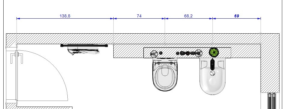
ViSoft measures automatically the dimensions between placed objects. It’s easy to add extra custom dimensions.
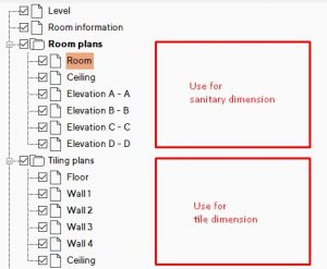
Take note: the first plan level is for dimensions on the outer walls.The room plans can be used for dimension within the room.
Manual measurements
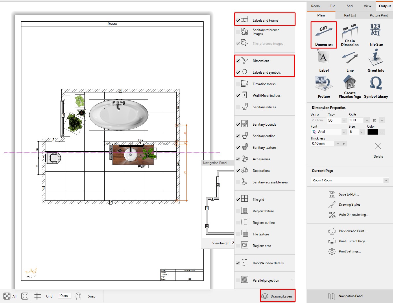
First of all, make sure that in the drawing layers the Labels and Frame, Dimensions, labels and symbols are checked.
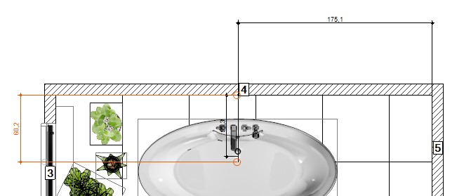
Use the button Dimension to measure the distance between two points. Activate the button and click on the first point. Hold left mouse key and release on the second point. You can move the line by dragging it.
In the right menu under Dimension properties,you can change the look of the dimension, size, font, color e.g.
Adjust the design with the DrawingStyles layer. The changes you make here will be saved as default. If you like to keep the style for the whole company, copy the settings from the folder ViSoftCreative/ userdata / settings.xml to other ViSoft computers.
Chain dimension
Use the button Chain dimension if you want to measure multiple points. Left-click on the points, for example, the heart of objects. Stop the chain with enter or double-click.
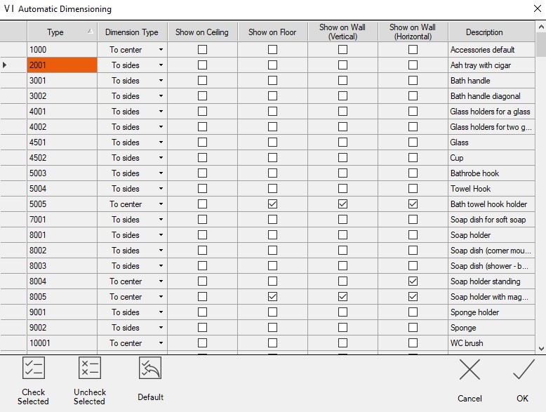
Auto dimensioning
It is possible to edit the settings for automatic dimensions. Click on the button Auto Dimensioning to open the table seen as below.
Each type of product is presented in a separate row. In the first column you see product codes. In the second column, select the dimension type: display in the middle or to the sides. In the third and fourth columns, you select whether the product type is displayed on the floor and ceiling plan. The fourth and fifth columns indicate if dimensions are shown on wall plans and elevations. Use CTRL or SHIFT to select multiple rows at the same time. Then use the button Check selected or Uncheck selected. Basic settings can be reset with the Default button.


 In the menu Output | Plan you find all the elevation pages of the room. Elevation pages are created automatically – one page for each wall.