In the project browser, you can right-click on a project and select Publish on ViSoft360. The project is stored in the ViSoft cloud and you can share it with coworkers. The upload process is exactly the same as publishing a panorama or image on ViSoft360.
Author:
ViSoft360 is a platform where users can share their designs. Directly from the media browser in ViSoft premium, upload your images and panoramas to your own ViSoft360 environment. Your customers can view the designs in their internet browser or with the free ViSoft360-app for smartphones and tablets. You can also display designs on your website.
Read here how to create images, videos and panoramas of your project.
How to upload, publish and share a panorama (and other media)
Step 1: Open menu View | Advanced to create a panorama. Select the
Step 2: Open the Media Browser (use button right menu), select the created panorama and click Publish on ViSoft 360.
Step 3: A new window opens, fill in the information of your project. Create a new album for your 360-environment if desired. Press upload.

Step 4: The ViSoft360 browser opens. Change the preview if you like, and select the Privacy settings. Press Save.
Step 5: Open the tab Share it. The option Email sends out a standard ViSoft-360 mail where you can type your own message. If you prefer to use your company email address, copy the link in your own email message to the customer. Or you can copy the PIN / QR-code if the customer uses the ViSoft 360 app. The app is free for download: iTunes or Google play store.
Registreren op ViSoft 360 www.visoft360.com
A ViSoft-User needs to register for a ViSoft360 account to get access.
Go to www.visoft360.com and open sign in page in the upper menubar. Click Sign up under the sign in button. Register and you can start uploading!


With ViSoft Phototuning you can render lifelike media of the project. This module needs to be activated separately from Premium. In ViSoft the rendering software V-Ray is integrated. Rendering is a graphical design term. To render relates to the processing of images for a film or animation.
A lot of elements are of importance in making a great render. Light settings are crucial, it’s important to create realistic lightning. Other important factors are camera position, used materials and textures, settings of the V-Ray rendering software.
Get started
Before you start with Phototuning, make sure you set up the lighting, materials, camera and viewpoints. The setting of light is certainly difficult at the beginning. Try to prevent setting the lights too bright and keep them behind or next to the camera. Start Phototuning in menu View | Advanced or use hotkey F10. The Phototuning preview window will open (see image below). The preview window is on the left side. The aspect ratio of the preview is equivalent to chosen picture resolution. Below it is the Exposure Correction slider. By using it you can make picture
By right clicking into the preview picture you can select three different ways for preview creation
- RT CPU: RealTime preview based on the processor computing power.
- CPU Production: render in the preview window, also based on the processing computing power.
- RT Cuda: Realtime preview based on the graphic card’s computing power.
RT CPU and RT Cuda are on-going progressive processes that keep rendering. First results are shown quickly. As time goes on more and more noise is removed. You may change the viewpoint or light settings at any time. The changes are detected and creating of a new preview begins. When using CPU Production you need to click
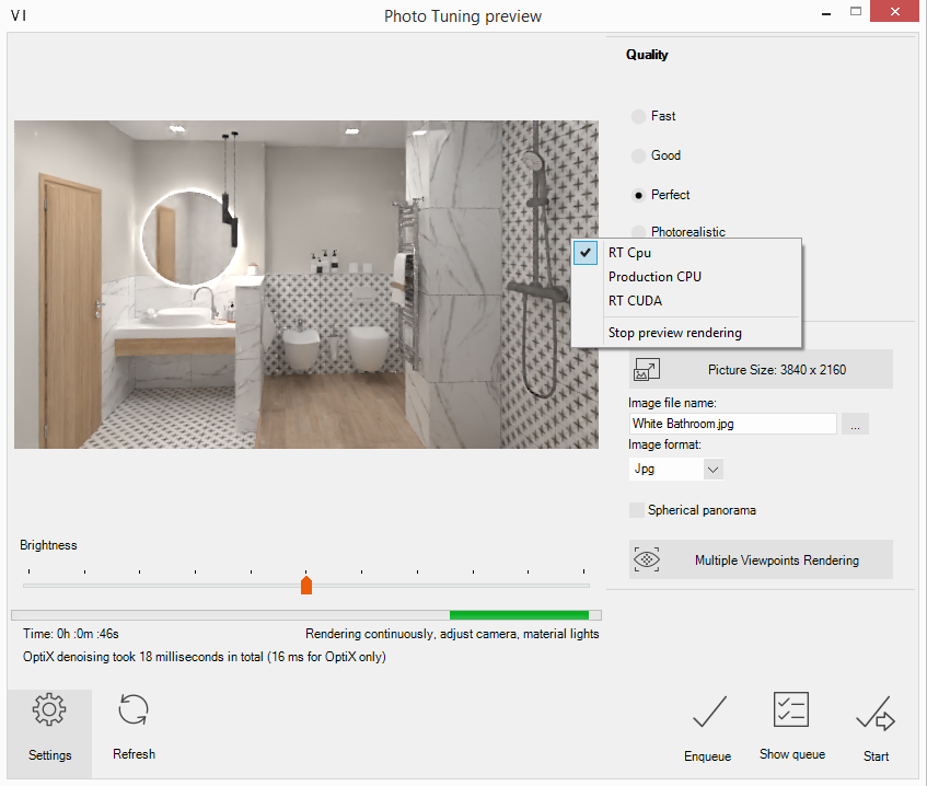
Quality provides four predefined quality options:
Fast
The setting fast doesn’t calculate soft shadows or natural lighting and leaves all quality settings on a low level. This mode is useful to get a fast overview of the brightness of all lights in the current scene. Use this mode always
Good
This level uses soft shadows with low quality and some other settings that increase quality. Use it to perform enhancements on details and to create pictures with low quality.
Perfect
This adjustment computes softer shadows with higher quality and increases other quality settings.
Photorealistic
This option calculates quality soft shadows. All other necessary quality settings have high values. You should use this mode when light and material settings have been already finished. The result of the automatically optimized settings is a

Use Output to select the resolution. Choose from the typical resolutions, or type a custom size in pixels. Think about the intended use to define the adequate resolution for presentation. Try to match the resolution of the device you want to present it on, go lower or higher and it reduces the quality. Read here more about how to calculate the DPI. Higher resolution means longer render time.
Under Image file name fill in the name of the image. Press … to change the save location. Use Image format to save to JPG, PNG or TIF. Enable Sferische camera if you want to render a panorama and use is for software like KRPano.
Press the button Multiple Viewpoints Rendering to select more viewpoints, and enqueue them all at once to render. In menu View | Camera
Explanation of the other functions: Refresh: the preview starts a new rendering. Enqueue: Add a task to the render queue. You can add tasks and start the renders at a later time. Show enqueue: open the
Settings:
Press the button Settings to set up the preferences for Phototuning. The ViSoft System Preferences window is

Use V-Ray frame buffer for rendering
Enable denoiser
diminishes the noise in an image.Vermindert eventuele ruis in een afbeelding.
Auto-exposure
Auto Exposure is an additional pass before the preview rendering starts. It detects
Glare Effect
Creates light beams around objects with high intensity.
Enable Chamfer Effect
Use
GI Saturation
GI Saturation enables
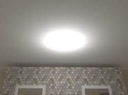
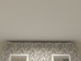
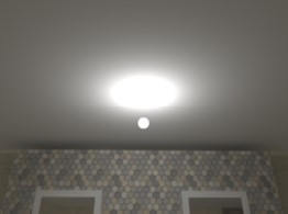
Not all light properties are visible in Phototuning. In the image below, the properties that are visible when making a render, are marked with orange. All properties are visible in 3D-view.

Recessed light source and visible in Phototuning
When the setting Use as recessed light source is enabled under special settings in the light properties, the light will be shown as a disc. If Use as
 Visible in Phototuning off: point light itself is not visible. |
 Visible in |
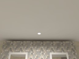 Use as recessed light Visible in Phototuning on: point |
 Visible in |
The default save location of the Phototuning queue is:
Dongle installations: C:\ViSoftCreative\UserData\VRay\ScheduledTasks.
Online license: C:\ProgramData\ViSoft\ViSoftPremium\UserData\VRay\ScheduledTasks
These folders can be copied for a backup of the
If you want to export a

It is possible to adjust the exposure and other processes after the rendering of an image. Open Phototuning (F10) and press Show queue. The V-Ray rendering queue shows paused or rendered images. Right click on a rendered image and select Post processing. The V-Ray frame buffer is opened. Make corrections for the exposure, contrast, colors, e.g.

Open the corrections control panel left bottom:

For
Exposure
This
White Balance
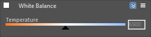
The White Balance slider corrects the colors in the image so that objects that are white appear as pure white (and not tinted blue, yellow, red, etc.) in the final image.
Hue/Saturation
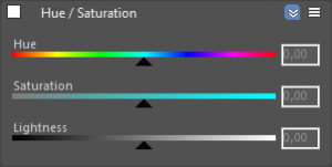
This correction applies HSL transformation on the image colors. Moving the Hue slider changes the overall hue of the image colors (grey colors remain intact). Lower Saturation values move the image towards greyscale while higher values increase the colors’ intensities. Higher Lightness values add white to the image, whereas lower values subtract white from the image.
Color correction template
It is possible to save your preferences in a template. Click on Global and select save. Save the Global Color Correction File (*.vccglb) on your computer. Load the correction file on other rendered images in your queue

More detailed information about the V-Ray Frame buffer and functions can be found on the V-Ray website:
V-Ray Frame buffer
Lens effects
How do I calculate the right image resolution?
For your printed matter, DPI (dots per inch, inch = 2,54 cm) is often specified as a quality requirement.
If you want to use DPI as
For what medium will the image be used and in what size?
For
We will use the following formula:
Width image:
(21 : 2,54) x 150 DPI = 1240 px
Height image:
(14,8 : 2,54) x 150 DPI = 874 px
Render the image in resolution 1240 x 874 to meet the 150 DPI requirement.
Under output in ViSoft
Default print DPI resolutions:
Billboard = 15 dpi
Magazine= 150 dpi
Fine art print = 240 DPI
Formula size in cm to pixels
Width image:
(width in cm : 2,54) x 300 DPI = pixel size
Height image:
(height in cm : 2,54) x 300 DPI = pixel size
Formula pixel to width or height in cm
Width image:
(width pixels : 300 DPI) x 2,54 = imagesize in cm
Height image:
(height pixels : 300 DPI) x 2,54 = imagesize in cm
Note: this formula is only a theoretical resolution and does not always apply. It also depends on the quality of the image.
Some manufacturers in the updatemanager are ‘locked’. To get access, you have to get permission from the manufacturer. Contact your agent or wholesaler: he or she will get the permission from the manufacturer. Communicate your ViSoft Customer ID to the manufacturer and ViSoft. You can find your Customer ID in ViSoft under Help > Registration info.
After receiving the permission forward it to ENTERMAIL to get access. The mail of the manufacturer needs to contain their logo.
When you have received the green light, download the brand with a rightclick > Start download immediately.

Step 1
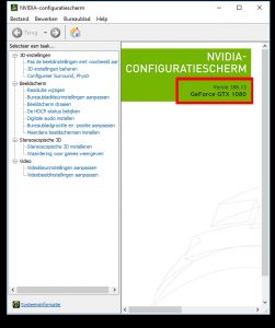
First, check which graphics card you currently have. There are 2 ways to do this:
1) Right-click on your desktop background (wallpaper) and > select NVIDIA-Control Panel. The application will pop up, this can take a while. In the ‘home’ screen is stated which Graphic card you have.
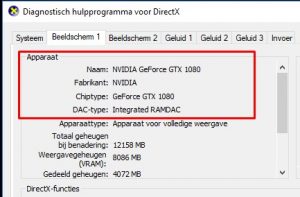
2) The second way is to use the diagnostic tool of Directx. Press Windows button + R and type dxdiag. Select Display 1 and under chiptype, you can find your graphics card.
Step 2
Go to the Nvidia driver website to download the newest drivers. Fill in your information an hit ‘search’. Next hit ‘download’.

Step 3
Open the downloaded installation file and follow the steps. After completion, your Graphics card is updated.
Before you start:
Check if you have administrator rights (if not, contact your IT-department) and if your antivirus software lets you install ViSoft. When in doubt, shut it off for the duration of the installation.
You can find the system specifications for ViSoft Premium here.
Close all other programs and make sure you have a stable internet connection if you are installing the online setup.
Send an email to info@visoft.de if you wish to receive an installation file to test ViSoft.
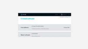
The installation:
Start the .exe file out of your download folder. Follow the steps in the program. After the installation, the pc needs to be restarted. Then you can start ViSoft P
Registration and activation without a dongle
Extend the following information when you are installing for online license. Otherwise, you can skip this step.If you are using ViSoft for the first time as a new customer you need to create a new account. Please use the same e-mail address as the one you used for ordering ViSoft.
Fill in all your contact info and hit register. After registration, you will get a confirmation mail, check your spam folder if you do not see it in your inbox. Using ALT + TAB you can switch to your email program (without closing the installation).
Log in.
After registration, you choose the option to try out. A rental (online) license works without a dongle. In this case, a stable internet connection is needed to start ViSoft. If you bought ViSoft with a dongle, plug it in now (you still select try out). A migration tool will appear in the update manager, which transfers your license to your dongle.
Remote Assistance
A ViSoft Teamviewer shortcut appeared on your desktop. This program allows us to log in remotely to your pc to assist you when you have a question or problem. Please start the Teamviewer application before calling. If you use an own TeamViewer, close it before starting the ViSoft one.
Firewall Settings
Your Firewall security might block the ViSoft update server. The following addresses need to be accessible for ViSoft to be able to install updates, grant them access in your firewall settings:
91.250.86.216 : Update Server
Libraries
After installation, you can start choosing which tile- and sanitary brands you want to use. In ViSoft, open the update manager and select the needed brands. You can close the update manager, it will keep downloading.
Projects path
In ViSoft under File > Settings > tab Common(
Network installation ViSoft data files
After the installation of ViSoft, you can choose to set some of the data in a network folder to share with multiple users.
All paths are saved in the settings.xml file in the Userdata folder.
The settings.xml can be changed on one pc and then be copied to all other PC’s with ViSoft installed.
Close ViSoft before you change the settings.xml file. You can find a more detailed explanation of network saves here.
| Network paths | Installation with dongle | Installation online (no dongle) |
|---|---|---|
| Software | C:\ViSoftCreative | C:\ProgramFiles\ViSoft\ViSoftPremium |
| Utils | \Utils | \Utils |
| Data | C:\ProgramData\ViSoft\ViSoftPremium | |
| Sanitary | \Arge | \Arge |
| Tiles | \tiles | \tiles |
| UserData | \Userdata | \Userdata |
| Projects | \Projekte | \Projekte |
Save location of Tile boards (Created with the board assistant)
C:\ViSoftCreative\Tiles\boards\
Save location of Tile patterns (Created with Tile > patterns)
C:\ViSoftCreative\Tiles\patterns\
Save location Murals Library (Grouped sanitary objects)
C:\ViSoftCreative\Data\CustomMurals\</custom_mural- folder>
Save location sanitary library
C:\ViSoftCreative
>The locally installed sanitary library can be found at c: \ViSoftCreative\Arge. Move all the folders to the network location. Don’t add Arge in the path, otherwise, ViSoft will create an extra
For example, F:\ViSoftCreative is correct, place the
See the latest specs here.
Some antivirus software or firewalls block the path to the ViSoft update server. If this is the case you will receive an error when updating.
Change the settings to allow the following addresses:
DEMO / ONLINE VISOFT PREMIUM:
services.visoft360.com
update.visoft.de
visoftonline.com
62.138.185.73 : main server
92.204.5.84 : reserve server
VISOFT INTERNET UPDATE:
dataupdate.visoft.de
91.250.86.216 : Update Server
V-RAY LICENSE SERVER:
| 5.175.6.211 |
| 5.175.6.213 |
| 5.175.25.71 |
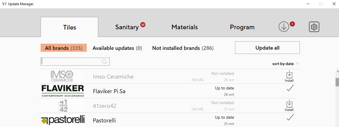
When first starting ViSoft, the tile, and sanitary libraries are empty. With the Update manager, you can download all the brands you need. You find the update manager in the top bar:
![]()
The following window opens. To the right of the brands, you can select to install or update. If there is a checkmark next to it, the brand is installed and up to date. 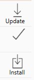
Rightclick on a brand to expand the extra menu.
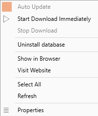
Auto Update: When checked, ViSoft will keep this brand automatically up to date. You can select a time to update in the Preferences > Update. (CTRL +K)
Open in Browser: Opens the brand in the browser.
Properties: Show the database properties of the brand.
Uninstall Database: Delete the brand from your libraries.
Some brands are locked by default, you can spot these with a lock icon next to them. For these, you need permission from the manufacturer to use them. Contact your agent or dealer to get access, send the permission mail to MAIL. The mail of the manufacturer needs to have their logo in it.
Include your customer ID as well, you can find this under Help > Registration info.
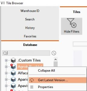
Updating from the sanitary or tile browser
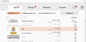
You can update brands directly in the tile and sanitary browser. The brand has an update if it has a red exclamation mark next to it. Rightclick on the brand and select Get Latest Version...
You can save projects and others on a network disk in order to have them accessible to multiple computers and users.
The network setup of the Tile library is described in this article.
On a local installation of ViSoft Premium, all the paths are in the file: c:\ViSoftCreative\Userdata\settings.xml
The file settings.xml can be altered on one pc and then copied over to the others to have the same settings on all PC’s.
Attention: Close ViSoft Premium before you change anything in the settings.xml file.
| save path | Dongle installation | Online license installation |
|---|---|---|
| Software | C:\ViSoftCreative | C:\ProgramFiles\ViSoft\ViSoftPremium |
| Utils | \\Utils | |
| Data | C:\ProgramData\ViSoft\ViSoftPremium | |
| Sanitary | \Arge | \Arge |
| Tiles | \Tiles | \Tiles |
| UserData | \Userdata | \Userdata |
| Projects | \Projekte | \Projekte |
Project location (visualizations and drawings)
In the ViSoft preferences > General, you can change the location of where the projects are saved.
By default, this is C:\ViSoftCreative\Projekte
Click on the 3 dots to the right to select your own path to save your projects in.
Projects path in settings.xml:
<projects-folder>C:\ViSoftCreative\Projekte\</projects-folder>
Save location of Tile boards (Created with the board assistant)
C:\ViSoftCreative\Tiles\boards\
Save location of Tile patterns (Created with Tile > patterns)
C:\ViSoftCreative\Tiles\patterns\
Save location Murals Library (Grouped sanitary objects)
C:\ViSoftCreative\Data\CustomMurals\</custom_mural- folder>
Save location sanitary library
C:\ViSoftCreative
>The locally installed sanitary library can be found at c: \ViSoftCreative\Arge. Move all the folders to the network location. Don’t add Arge in the path otherwise, ViSoft will create an extra folder. For example, F:\ViSoft is the correct path, place the Arge folder in here.
The ViSoft with dongle installation is placed on the C: disk in the folder ViSoftCreative, including the tile and sanitary libraries.
An online license is placed on the following C:\ProgramFiles\ViSoft\ViSoftPremium and the data in C:\ProgramData\ViSoft\ViSoftPremium\.
After the installation, you can move the tile library accordingly to the following steps.
Close ViSoft Premium before starting this process.
Tiles:
Move the folder C:\ViSoftCreative\Tiles\Fliesen (DONGLE) or C:\ProgramData\ViSoft\ViSoftPremium\Tiles (ONLINE) to the new location of choice. For example on your D: disk create a folder Visot_Tiles. If you have all brands installed (don’t do this) the folder will be 31GB so it will take some time.
Now you have to change the path in the settings.xml file to the new location.
Locate the file in c:\ViSoftCreative\Userdata (DONGLE) or C:\ProgramData\ViSoft\ViSoftPremium\Userdata (ONLINE) and open it in notepad.
Find the line with the tiles folder:
![]()
and change it to the new path:
![]()
Attention: Don’t include the Fliesen folder in the path.
Start ViSoft and select the new location in the pop-up.
You are done!
For changing other paths read this article.
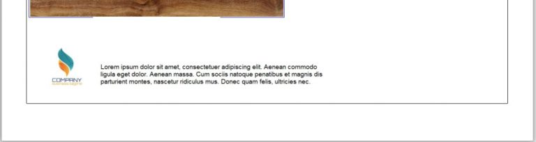
For the outputs, you can set a corporate identity using logo’s, footnotes and text labels. These settings are saved for all new projects. It can happen that after an update the settings are removed.
Adding a logo
In the output select the Print Settings. In the menu select the button with 3 dots on it to add a logo, you can use a BMP, JPG or GIF file. Check the box above the logo on the position you want to use. The numbers accord to the left (1), middle (2) and right (3) of the page. You can also select if you want them on the top or bottom of the page.
![]()
It is also possible to add a logo with/or only text, for example, to have add disclaimer and a logo. In the example size 850px-115px is used.

Footnote
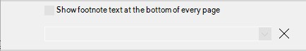
Another way to add a disclaimer is to use a footnote. This can also be found in the print settings. This footnote can only be 1 line long and will be shown on every page.


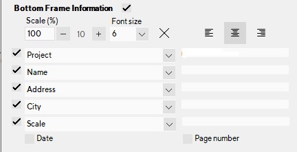
Bottom Frame Information
In the Print Settings, you can turn on or off the Bottom Frame Information. you can also add the information to the frame and check or uncheck what you want to be displayed.

Attention: make sure you have the option labels and frames checked in the Drawing Layers.
Laptop with an extra dedicated graphics card needs an extra few steps to make sure ViSoft uses this card.
Step 1: Install Nvidia GeForce Experience From Nvidia’s website: https://www.geforce.com/geforce-experience/download
Step 2: Login with 1 of the possible accounts:
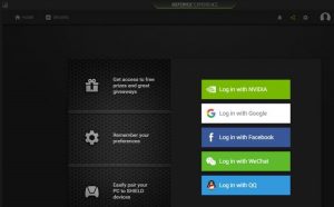
Step 3: Download and install the latest Drivers:
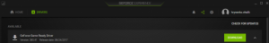
Step 4: Restart the laptop
Step 5: Navigate to the NVIDIA control panel (right click on your desktop)

Step 6: Go to Manage 3D settings.

Step 7: In Program settings, Add Visoft to the list if it is not there.
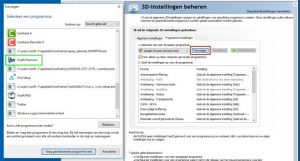
Step 8: Set the graphics processor on the Nvidia processor.

Your laptop is done!
Use the ViSoft Backup Tool to archive or to make a backup of your data. Make sure ViSoft Premium is closed. The BackUptool.exe can be found in the folder ViSoftCreative on a local hard disc (c:\VisoftCreative\). Archives can be made of projects, custom tiles, objects, baskets, auto boards, prices… The ZIP-files can be used to restore data.
Mark the data you want to save in the archive file and select create backup. Select a folder and archivename. The packing process can take a little while, depending on the size of the data.
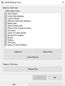
To restore data, click Restore files and select the archive zip file. This could also take a while, depending on the size.
It is recommended to make a backup regularly. Best to use multiple save locations, like an external disc, NAS or the cloud.
Plug in the ViSoft Premium USB dongle in to one of your USB ports.
When starting ViSoft premium for the first time it will need a activation code. This activation process is done automatically a problem occurs. If there is a problem a activation screen will pop up, please enter all info except HardwareID. You can find your customer id on your invoice.
You can get a activation code in a few different manners:
Online activation: Click on the button to get your code online.
Via e-mail:
Via Phone: Click on the button by phone
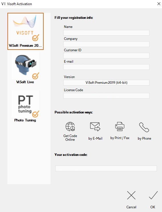
Select the Ok button.
When you have multiple work spaces you need to do this process on each pc.
No e-mail client on your ViSoft computer? Send a e-mail to lizenz@visoft.de from a different pc:
Bitte freigabe für:
ViSoft Premium versie xxx ( Add your version on the xxx; e.g. 2018-64 bit.)
Hardware ID: xxxxxxxxxxxx ( in here copy the harwareID in the activation screen)
You can add silicone in the Output – Part List – material. Click on the button Add Predefined Entries, find Silicone in the list and tick the box Add to part list. Select apply to close the window.

The needed amount of silicone is calculated automatically and added in the part list. ViSoft calculates for the floor the outside edge of the tiled area. For walls, it calculates the length between walls and outside edges of connected murals.
You can also add the needed wall and ceiling colors or stucco in the Parts List.
Before you start the setup of Oculus Rift VR, check if you have the following stuff ready: 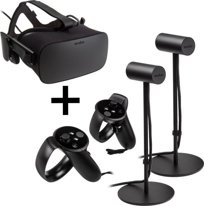
– Rift (glasses)
– Touch Controllers
– Sensors
– AA batteries
– Audiotool
PC:
– 3 free USB ports
– 1 free HDMI input
– 10,2 GB space free for software
– SteamVR software (downloadlink First, install the regular Steam, then install Steam VR)
Physical space: space to move and stand-up.
Step 1
When you use the Oculus Rift set for the first time, untie the sensors and put AA batteries in the controllers.
Step 2
Go to oculus.com/setup/ to download the Oculus Rift software. Start the setup and follow the installation steps. Create an Oculus Rift account.
Je dient een Oculus Rift account aan te maken. Stel een foto en een pincode in.
Step 3
During the installation process, follow the steps to set up the Rift, sensors and controllers.
Step 4
Start ViSoft Premium and go to View | Advanced and start Visual Reality. ViSoft checks if Oculus and Steam are installed and starts the software automatically. It’s very likely that you will get the pop-up from oculus: ‘unknown source’. Follow the next steps
Allow content from unknown sources :
- Open the Oculus app on your computer.
- Select Settings in the left menu.
- Select the General tab .
- Click next to Unknown sources to allow content from unknown sources.
You ready for VR!
You can change the visibility of objects in the menu Output | Plan. In the ceiling plan when you open the navigation panel you can change the View Height.
In the following example, the view height is set on 160 cm. Objects that are above this height will then be displayed in the ceiling plan.

If you set the view height above the objects they will appear in the room plan.

Photofiltre is a free photo editor, that you can use instead of photoshop. Download the installation file here.
There are different language packs if you want to have a different language than English.
Read the explanation on how to create a transparent background for nonrectangular tiles image here.
The Light Templates function calculates automatically a lighting plan for the room.
It places Fill- and Focus lights.
 In the menu View | Light you select Light templates…. On the left side of the screen, a few example templates will appear that you can choose. You can also create your own template with the Create button.
The Fill lights are the normal lighting for the room.
Focus lights are for highlighting certain spots in the room. for example hollows, basins and walls.
Select the wanted brightness, IES Light Profile, and spacing. you can also select which lamp to use.
In the Explorer of the side browser, you can select light groups, move them, change properties or delete them.
You can rotate an object a few different ways. When placing an object from the sanitary browser you can use the following hotkeys to rotate them while placing:
- ALT aligns the object to the wall.
- CTRL rotates the object on its axis.
- SHIFT locks the horizontal axis, this way you can move an object up or down.
Another way to rotate an object is to use the modify object function.
Example
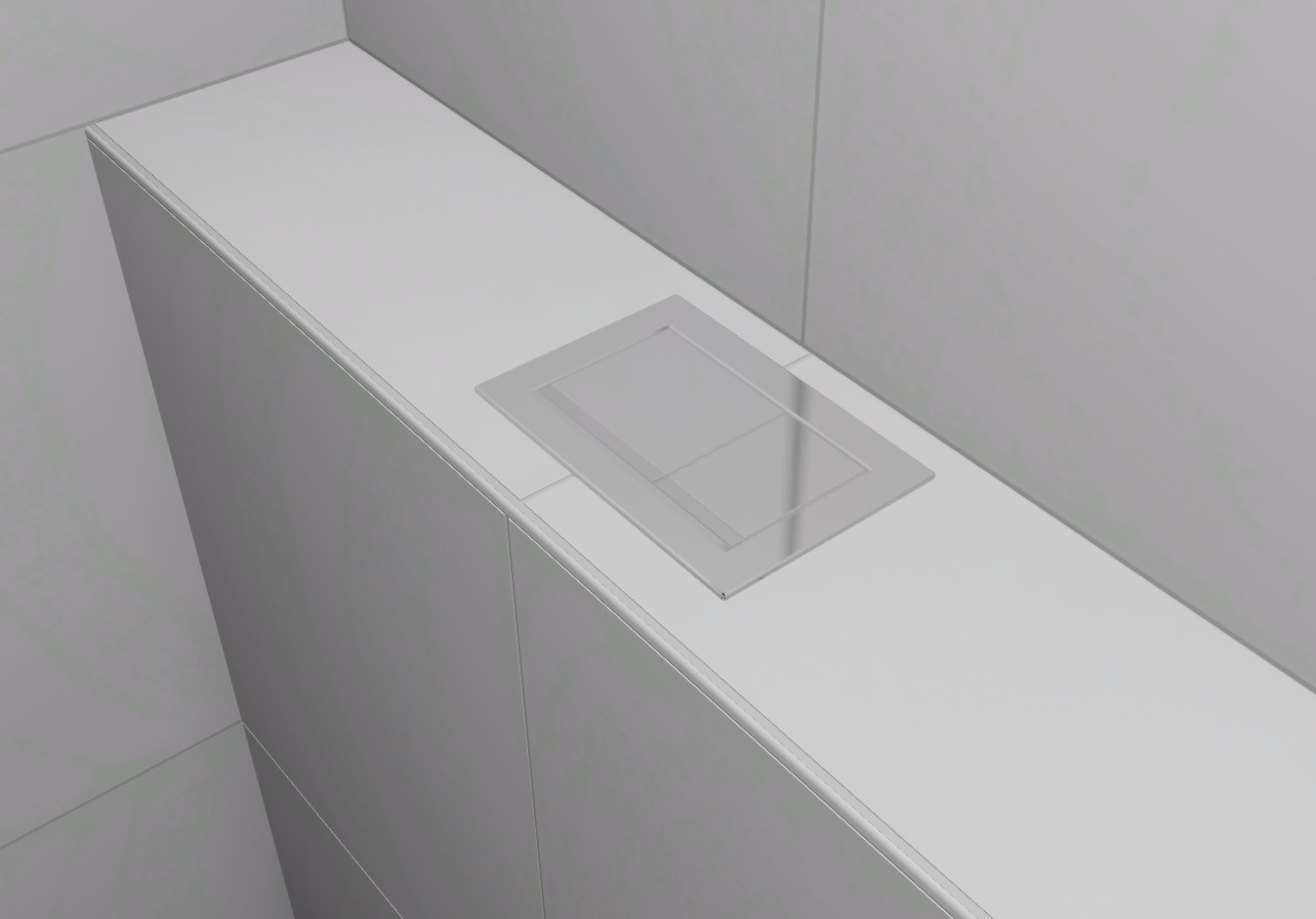
If you want to place a flush plate flat on a surface. First try it with the hotkey Alt, if this doesn’t work use the modify object function.
In the modify object menu select rotate and turn it around the correct axis.

Now you can change the Mounting height and the distance X and Y in the object properties to place the flush plate perfectly on the surface.
In the menu Tile | Edges you can place profiles on one or more external corners. Rightclick on the profile button to open the Profile Browser. The database of edge profiles contains data of manufacturers Schlüter and Proline. The articles are separated by base material (e.g. aluminum, stainless steel, PVC). When a product is selected available heights are shown in the list beneath. You can also select the surface material (when several materials are available).

If you place a profile on an edge, make sure that 3D tiles are shown to see the tile thickness (context menu > 3D-settings > 3D tiles).
TAKE NOTE: not all manufacturers include the tile thickness in the database, the default is 5mm. Another issue could be that various tiles with different tile thickness are used on edges. You will have to place profiles manually.
If you use one profile on all edges, choose the Place to function from the right menu.

It is possible to place a profile in 2d or 3D-view. If the corner turns red, the edge is not right-angled.
Some profiles types can be ‘flipped’. Select the profile, open the context menu and select Change overlap type.
To start the VR-module, go to module View | Advanced. Press the button Virtual Reality.
Select camera position center, so you have a good view of the space at eye level.
Make sure the HTC Vive software or Oculus Rift software is installed.
It can happen that transparent objects are displayed a bit weird on renders.
This situation occurs when normals of the transparent object-oriented inward, so Photo-Tuning engine cannot calculate glass material correctly.
To solve this difficulty normals of the object need to be recalculated and then flipped to achieve the proper orientation
Example of a shower screen:
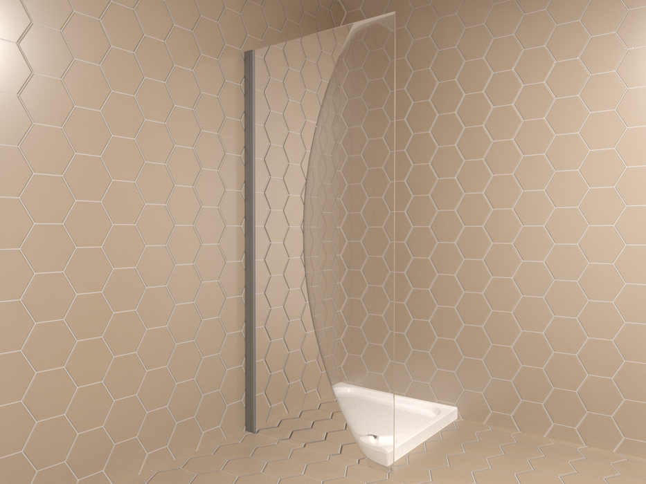
You can solve this issue with the Modify object function in the Sani menu.
In the modify object window, first select recalculate normals, set Smooth threshold to zero and click on apply.

Second, select flip faces and apply.

The render after correction:
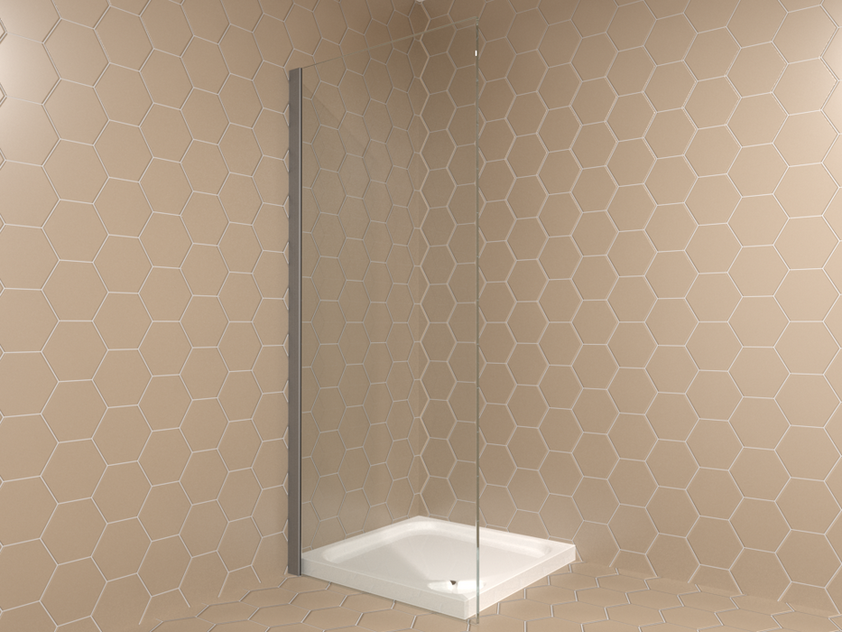
If this doesn’t work, try to reduce the reflection of the object. In menu View | Material select the object material and then reduce the reflectivity in the parameter menu on the right.
Global Illumination (GI) is one of the visualization effects that you can control. The exposure in your project should improve a lot just by turning on this feature. GI refers to a scene where the lighting is reflected around and on objects (indirect lighting). This feature provides secondary light beams, creating a pleasant and balanced exposure.
Configure the GI function in menu View | Advanced.


Left: No GI. Right: GI is on
Note that: Global Illumination doesn’t show in PhotoTuning renders. This article described which light settings affects your rendering.
Use a block mural to create a balcony in your project. Enable the function free edit ![]() in the lower toolbar so the block can be moved outside the walls of your project. Drag to block outside the walls and give it the right properties in height, width etc.
in the lower toolbar so the block can be moved outside the walls of your project. Drag to block outside the walls and give it the right properties in height, width etc.
The project shown above can be downloaded here. Import the project File > Import > Import project from archive.
To edit the tile properties, open the explorer on the left. Make sure you work in menu Tile | Place | Tiles.
Rightclick on the tile to open context menu and select Tile Properties.

For example, you could set the edge radius under material.

Make sure you have the 3D-tiles and 3D-border view on to see the effects ( Menu View | Advanced).

The HTC Vive comes with a lot of hardware and accessories. But how do you ensure that you get started as soon as possible? On this page you can read how to connect, install and adjust the HTC Vive, so that you enter the world of VR as comfortably as possible.
What do you need to install the HTC Vive?
- The complete HTC Vive package
- An internet connection
- A ruler
- A mirror
- At least half an hour free time
- Optional: 2x tripod + 2x connector
** Attention ** Make sure that you always keep the lenses of the HTC Vive out of direct sunlight. This way you prevent a burned in screen.
Step 1: Connect
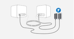
Connect the base stations
- Place the supplied mounting brackets in the wall at least 2 meters high, up to 5 meters opposite each other. You can also opt for a tripod or bookshelf,
- Place or screw the base stations at the chosen location. There must be nothing between the 2 base stations.
- Connect the base stations to a power outlet using the supplied power adapter. They need an unobstructed view of each other.
- Remove the protective film from both base stations.
- Do you see a green light and the letter b and c? Then they are well connected! Do you see a purple light? Then use the supplied sync cable and switch with channel from channel a to channel c.
Connect the VR glasses
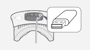
- Take the link box out of the box and connect it to the socket with the power adapter.
- Connect the link box to your VR pc or laptop using the supplied usb cable.
- Connect the link box on the other end to the HDMI output of the video card in your PC or laptop with the supplied HDMI cable.
- Connect the 3 cables coming from the HTC Vive to the other side of the link box.
- Remove the protective film from the HTC Vive.
Step 2: Install the play space
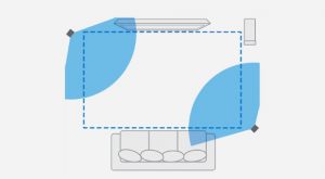
Option A: standing. If you have an empty space of at least 3 x 3 meters at your disposal.
- Remove all tables, chairs, pets and children from your play area. \ n2. Make sure that floor is free so that you do not stumble anywhere. \ n3. Place your VR PC or laptop outside the playing area. \ N4. Make sure that sensors are properly aligned with the chosen area and can see each other. \ n5. Clearly plan the area during the software installation.

Option B: sitting. If you have a limited space at your disposal, or simply prefer to sit during VR.
- Put the base stations at least 1.5 meters apart, with a seat in the middle.
- Make sure that all objects are at least an arm’s length away from you when you sit on your chair.
- Clearly plan the area during the software installation.
Step 3: Installing the PC or laptop
Video card drivers

- Download the latest drivers from your video card. \ N * Download NVIDIA drivers \ n * Download AMD drivers \ n2. Open the file and follow all the steps in the installation process. \ N3. Restart your laptop or PC after installation.
HTC Vive software
- Download the HTC Vive setup file. This includes the Vive desktop app, Vive Home VR experience and the Steam client. \ n * Download the HTC Vive setup \ n2. Perform the setup on your VR PC or laptop. \ N3. Make sure you go through all the steps of the installation process. \ N4. Now your PC or laptop and the HTC Vive understand each other and are ready for use.
Step 4: Adjust
** Adjusting the headband **. Naturally you want to get as comfortable as possible VR with the HTC Vive. Make sure that the headband is properly adjusted.
- Put the glasses on your head and pull the headband at the top back until the glasses are firmly on your head.
- Use the Velcro on the side to loosen or tighten the glasses.
- The HTC Vive sits comfortably on your head when the VR glasses are pointing forwards, not upwards or downwards. To show the image sharply, you can get started with the Interpupilar Distance, the distance between your pupils, and the lens distance relative to your face.
Adjust the lenses and the lens distance
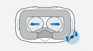
Adjust the lenses to your IPD
IPD – your Interpupilar Distance – is the distance between your pupils. It affects the way you focus your eyes in VR. The Vive is calibrated for most IPDs, but some people may experience a blurry image with the default settings. This way you can adjust the VR glasses to your IPD.
- Stand with a ruler as close as possible to a mirror.
- Look straight into the mirror and keep the ruler at eye level against your face.
- Write the distance in millimeters.
- Put the HTC Vive on your head.
- Adjust the distance between the lenses with the button on the bottom right of the VR glasses. \ N6. Turn the knob until you see the correct number of millimeters.
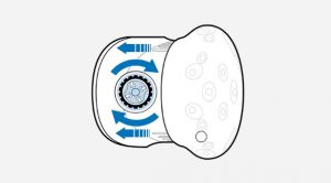
Adjust the lens distance
The lenses may be too close to your face because you wear glasses, for example, or have long eyelashes. In that case, adjust the distance between your face and the lenses.
- Pull out the 2 rings on the side of the HTC Vive.
- Put the VR glasses on your head.
- Turn the knobs to move the lenses closer to you or further away from you.
- If the lenses are clear of your face, you have the lens distance well adjusted.
If you want to share a Visoft 360 panorama on Facebook, you need to edit the (Efix) metadata of the image so it gets recognized as a 360-photo. You can check the Facebook 360 documentation here.
Step 1
Use Phototuning to render an image; set the resolution to 2:1 (e.g. 6000×3000) and enable the option Spherical camera.

Step 2
For editing the metadata you can use the online tool The Exifer.
Drag & Drop the image created in ViSoft to this tool and press eXif.me.

Browse to the last tab named xmp gpano tags and scroll down until you see ProjectionType (4th from bottom).
Fill in: equirectangular. And press Go.eXifing.

The metadata is modified, close the editor.
Press download.me to download the image with the new metadata.
The image can now be uploaded on Facebook as a 360-photo.
In the menu Output, you can add a footnote in the print settings. This footnote is one line and will be printed on each page at the bottom. If you want to use more text, use an image containing the text.

In the printer settings in the Output menu, you can add the Bottom Frame Information. You can change the scale and font size of the frame and check which lines you want in it. The information for the frame can be entered here as well.
If you want to change the name, address, City information you need to do this in File > customer info.
Attention: have Labels and frame turned on in the Drawing layers to have the Bottom frame information visible.
In the output select the Print Settings. In the menu select the button with 3 dots on it to add a logo, you can use a BMP, JPG or GIF file. Check the box above the logo on the position you want to use. The numbers accord to the left (1), middle (2) and right (3) of the page. You can also select if you want them on the top or bottom of the page.
![]()
It is also possible to add a logo with only text, for example, to have a disclaimer in the logos. For this use about a size of 850x115px.
Click on the Label button to add a text label. In the menu on the right in Text Label Properties you can change the text, font, layout, angle, and color of the text or frame.

After you made your label you can save it to the library. Right click on the label and select save to symbol library\labels. In the Symbol library, you can find the label folder on the left, the saved labels are in here.
Using the button Picture in Output you open a windows folder to find the picture you want to add. After you placed a picture you can move, rotate and scale if you double click on it. You can also do this in the Symbol properties menu on the right.

Murals can be used to create a furniture piece with washbasin. When you have designed your own sanitary object with murals, you can save it in your own database in the sanitary browser. Skip steps 1 to 3 if you have your mural object ready.
Step 1
Place a block with the following properties:
Width: 50 cm
Thickness: 120 cm
Height: 10 cm
Mounting height: 60 cm
Step 2
Draw a free hole on the block. Set the grid on 1 cm so you can accurately draw the opening. Set the depth of the hollow at 8cm, to create a bottom of 2 cm.

Step 3
Rightclick on the mural and select Save to library or Save to custom database. When you choose the latter, the object is saved without properties in the sanitary database under .custom objects > default. You can copy the object to another serie and edit the properties (from context menu). If you choose to save to library, the window Save Custom Mural opens. Click on the export to file… button and save the ViSoft3D-file on your computer. Press cancel.

Step 5
Open the sanitary browser. Open a serie from the .Custom objects database.
Rightclick > Add object. Fill in the properties, like the mounting height and mounting pivot.
Pivot = 0: bottom, Pivot = 1: Top, Pivot = 0.5 the heart.
In the article Edit objects you can read how to change the material and geometry of a custom object.
Materials such as the fabrics of towels contain ‘maps’ to create a realistic view. In this article the concepts of diffuse maps, bumpmaps and displacement maps are explained and how to use it in ViSoft. The effects are mainly visible after rendering with phototuning.
There are two ways to add maps to an object.
1) Add or copy the object to .custom objects in the sanitary browser. Open the Object properties. Go to tab material and open advanced parameters. Open the objects parts browser or select the material you want to edit in the preview. Now you can load/edit maps.
2) Open menu View | Material and select the material you want to edit. Under simple and advanced parameters you will find the maps.
Diffuse map
A diffuse map is a texture image that contains a colormap, like the image below.


Bump map
Bump mapping is a technique in 3D-visualization to simulate details such as bumps and wrinkels on the surface of an object. A bump map contains a gray-scale image of the texture. The detail that is generated is simply an exposure trick, polygons are not actually added to the 3D object.

A round object without maps.

The texture gives the illusion of depth on the ball.

Displacement map
When a displacement map is used, the texture of an object is actually adjusted. Instead of a depth illusion such as with bump mapping, the texture is ‘moved’: depth and height are added to the surface to create relief.
The displacement map below is used on the ball and gives the following result after rendering in ViSoft :


Compare the different effects of the bump and displacement map in the image above. The same texture is placed as a bump map on the front ball. On the second ball, you can see the texture of the displacement map again.
Thee website 3D Textures offers free and complete texture sets with displacement maps, normal maps, diffuse and more.
On vismats.com you can download a lot of free material images. You can import the images as custom material in the Material Library.
 Use menu View | Advanced for creating photos, videos, and panoramas of your project.
For the presentation of your project, you could use the animation. Select viewpoints you would like to use. If you used the navigation panel to save custom viewpoints, these will appear for use as well. Best to start in the middle of the room, to avoid hidden walls. Use the arrows up and down to change the order. Use speed to slow or speed up de change of viewpoints. Start the animation with the play button. If Repeat is activated, the animation starts automatically again after the last viewpoint. Use F11 to open/exit full view screen.
The animation can be saved to a video. Use the button save video to publish on ViSoft360, hard disc or YouTube.
Use the Fly Around button to start an animation around the space. Use the lower taskbar to activate Auto-hide walls and right-click to auto-hide connected sanitary or murals as well.
With Visualization effects adjust reflections, shadows and the global illumination. Lower the settings or disable the visualization effect if your graphic card is giving trouble. The same goes for 3D Settings (use context menu to disenable).
Use the button Save picture to save a JPG or BMP file of your current view. You can save a panorama to create a 360 image of the room. Set the viewpoint in the middle of the room, then press save. The window Panorama rendering opens.

Phototuning is an extra module, to render lifelike images. The Media Browser shows all the created images and gives fast access to ViSoft360. You can choose which rendering engine to use: 3D, phototuning and virtual reality. Select a folder to save the panorama. Create make to render a panorama.
In this article you can read step by step how to upload media to your ViSoft360 account to share it with your customers.
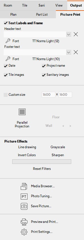
You can print images from Output | Picture Print
In the menu on the right, you can add Labels, a Frame, date, project name, tile images, and sanitary images. You can also choose a Custom size and Picture effects if you want.
When you have selected the wanted view and options to print. select the button Preview and Print. this shows you a preview of your print. Parallel Projection
With the parallel projection, you can make a 2D image instead of a 3D image. Click on Parallel Projection, and use the buttons and arrows to find the view you want. Saving a Picture
Multiple viewpoints can be saved as a JPG or BMP file. Select Save Picture and choose which viewpoints you want to save. You can set the Picture size, image quality, the file type, and a picture effect. At the bottom of the window, you choose the path and name of the picture.
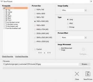
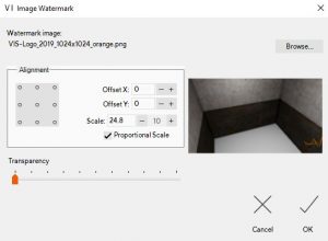
You can add your own watermark to the image by ticking the box; Add watermark image. once you ticked the box you can configure the watermark. select the image you want to use for example your logo in a .jpg or .png format. you can also choose the alignment, offset, and scale.
The sites listed below have interesting information and 3D objects to download.
(Click on the logos to go to the site)
| Information about new objects, mostly furniture. also 3D-objects for download | Free | |
| Millions of 3D objects available for download, using drag & drop you can put them directly into ViSoft. | Free | |
 |
A lot of architectural objects but also lighting and furniture. | Free |
 |
Mostly architectural objects but also textures | Free |
| Objects like Baths, Basins, and faucets | Free | |
 |
Design Furniture | Free |
 |
A mixture of 3D objects | Free |
| A mixture of 3D objects | $ 49,95 per year | |
| Materials and 3D objects | Free | |
| 3D Export | Free 3D objects | Free |
| Texture Haven | High-quality textures free for download | Free |
| HDRI Haven | High-quality HDRIs free for download | Free |
Take note: a 3D object should have a maximum 25,000 polygons.
The following file formats can be used:
-
- Autodesk 3Dstudio (*.3ds)
- WaveFront Object (*.obj)
- Collada (*.dae, *.xml, *.zip)
- DirectX (*.x)
- Blitz3D (*.b3d)
- WRML97 (*.wrl; *.wrz)
- *.dwg
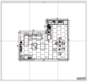
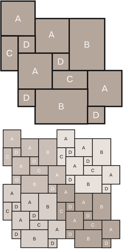
Sometimes it can be beneficial to print a large plan across multiple A4 pages. You can use the print preview to view how it is going to divide the print.
Set the scale of the plan in the Print Settings. select a custom scale, for example, 1/20.
The image below is an example of a plan that is divided across 6 pages. After printing this you can align them up using the guide marks.
In the Output menu, it is possible to add empty pages to create your own plan. Use the button Create Empty Page to get an empty page. You can add plans by dragging them in, or you can add labels and pictures from the right menu. Or, use the context menu to insert a plan page or picture.
![]()
![]()
This article explains:
– how the material library is set up
– How to add custom materials
– How to make slabs with the Natural Stone Assistent
The material library
Open the material library (menu Tile | Place | Material). The material library contains various materials like wood, plastic, metals, fabrics…
The materials can be placed on any kind of surface in your project.

The leftmenu contains the database structure with all the various materials. For some materials, e.g. wallpaper, you can set the texture and color.

Press OK. The cursor transforms in a pencil, click on the desired surface to apply the material. Hold CTRL to continue applying the material on other surfaces.

Adding custom materials
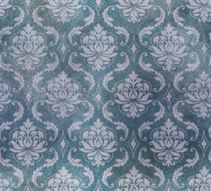
Use the .custom materials database to add your own materials based on images. Take note the images show seamless patterns, like the example below. When the material is applied no seams are shown.
Below we show how to install a color library. ViSoft doesn’t have a contract with RAL, but it is possible to add the RALcolors in your custom library.
Install color library
Step 1
Open the material library. Rightclick and select add serie.
Fill in the name and description and press OK.
Step 2
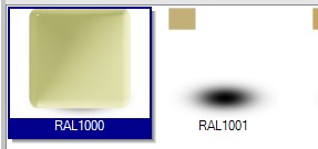
After creating the serie, right-click in the white space and select create material from image. With CTRL+A you select all the images in the folder. Press open.
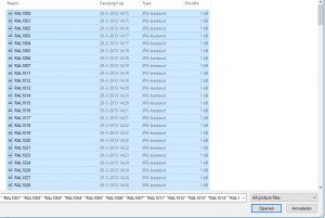
It takes a little time for all the colors to load. Rightclick on the color to edit the properties, like the type of preview.
Natural Stone Assistant
The Natural Stone module can be started with a rightclick under the menu Tile | Place| Tiles. The assistent can be used to make multiple tiles from a nature stone image. A different kind of tile image is possible as well.

Retrieve the image of the nature stone from the Material Library. Press Select Source Image… to choose the one you want to use.

Activate Random flip and Random orientation to change the direction of the tiles to make it appear more natural. If desired, adjust the size of the tiles. Set the parameter for the total the number of tiles. The ‘processed’ tiles appear on the left side. To delete one, rightclick and select Delete. The tile pattern can be saved, use the Save in Library… button to do so.

Sometimes it is necessary to rotate an object; e.g. a handle from HEWI.
Go to menu Sanitary and click button Modify object. naar menu Sanitair en klik op de knop object bewerken. Click on button Rotate. Under modifier options change the rotate degree on Y.

Export project to archive
Read more about creating a zip file of a ViSoft project.
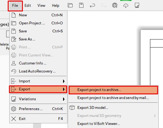
Use this function to export the projects that you made in ViSoft Premium. This can be useful if you want to transfer the project to a different pc with Visoft installed. Attention: this needs to be the same version as the one you made it with for example premium 2018. In the same way, import projects in ViSoft; File > import > import project from archive.
You can send the zip files via WeTransfer as they are most of the time too large for e-mail.
You can also use this function to create a back-up for your projects.
Exporting to CAD-software
Read more about exporting an image for editing in cad software.
If you want you can export a plan or a different output view to for example Autocad to add plumbing measurements.
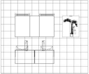
Below you find an example of a 2d image export opened in DoubleCad.
Go to File > Export > Export 2D image to CAD file

Downloads
Free Autocad and Bimviewers
Overview of free BIM viewers: https://blog.capterra.com/the-top-6-free-bim-software-tools/
A deep link shows product information on the website of the manufacturer or wholesaler. It uses the order number to show the product properties on the site.
In the sanitary browser select an object, click on the button Extended Info and open the deep link tab.

To set up a deep link, right-click on a manufacturer, and select properties.

A new window opens. Click on the Deep link settings icon.

Enter the Deep Link, e.g.: https://pro.hansgrohe-int.com/suche.htm?searchtext=
If you have a login and password, copy the example.
Now the products are linked; making quick access for ordering possible.

Use the submenu Light to adjust lighting in your project. Sometimes you will want to make your project or part of it brighter or darker. Besides
ViSoft Premium uses four different types of lights:
Point lights: equally dissolving inner lights;
Spotlights: narrowly shaped inner lights creating a circle with a thin ray of light;
Portal lights: outer lights entering through apertures such as windows, doors or holes; independent of the sunlight;
Sunlight: outer light source entering through apertures, which casts shadows in regard to its position.
Point lights are set automatically by the program in regard to the shape and size of your room. Portal lights are also set automatically for each aperture. You may manually add additional point lights as well as spot lights. Each light can be switched on / off. You can also set properties like position, radius, brightness and color for each of the lights.
Position of light sources can be set in 2D views Floor and Wall or in 3D. When setting brightness it’s recommended to switch to
By clicking the button Inside Lights all point and spotlights that exist in your projects are enabled. When you click button Sunlight you will switch off all of the point and spotlights. Portal lights of windows and holes will be enabled as well as the sunlight. You may still manually switch the sunlight and all other lights on or off and use them in any combination.
Use submenu Lights to set point, spot and portal lights. Use submenu Sun & Sky to set the position and brightness of the sun as well as sky settings.
Light tab
Use the button Point Light and Spot Light to place lights in the room. Use the properties to edit color, brightness and radius amongst other things. Global highlight sets the general light value.
The button Properties opens the window Light properties with extra settings, as temperature and IES light profiles.

Turn drop shadow on or off. Use Temperature for a warmer or colder color (Kelvin: below 5500 is warm, above cold). IES light profiles create a realistic bundle of light. The profile you choose is visible both in 3D-view and in Phototuning.

Display light cones in 3D (spotlights only)
Setting the lights is often a precise job. To see the effect better, enable a high light selection. In 3D-view open the context menu (right-mouse click), select 3D settings> highlight selection. The direction and radius of the spotlight

Sun & Sky
Position of the sun’s rays can be viewed in 2D floor view. This makes it easier to adjust the position of the sun. On the image below you can see how the sun’s rays come in (the yellow areas).

If you want to replace the background in ViSoft with an image, sky or 360-photo, visit this article.
If you work with a tile that only has one image and isn’t completely symmetrical, you can set the sorting to random. This function is accessible in multiple ways…
ViSoft Preferences
In the preferences (shortcut CTRL+K) you can set the default tiling orientation to random. 
Ways of tiling
In the menu Tile | Place | tiles you can select random orientation under tiling orientation. If you open the pattern assistent with the Ways of laying tiles button, you can also select which orientation you want to use.

Module Assistant
Open the Module assistant (button menu tile or in tile browser). Set the parameter to random.

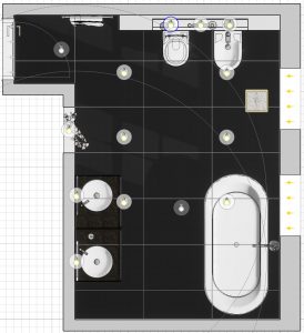
With the ViSoft Live module you can present on a 2nd monitor, flatscreen, TV, or other projectors.
Start the Live function in the upper toolbar View > Livingwall or use F8. On the second screen the live view appears + the toolbar below:

With the first buttons, you control the type of display: Display 1, Auto, Wallboard, 2D and 3D. Use the Auto mode to change the view automatically according to the menus you work in. Wallboard presents the tiling of a wall. In menu Tile | Fast you can change the wallboard: choose other tiles and patterns.
In preparation make tilesets of the tiles that are presented in the showroom, so you can quickly browse through the showroom assortment using the auto-boards. Various brands have included standard tile sets.
Browse through brands / Browse through tileseries (based on tilesets) / Browse through various tiling patterns
Read here how to create a wallboard. While you design a wallboard, the customer watches the design process on the second screen. This image can also be projected in actual size with a projector set-up (living wall). The floorboard works in the same manner.
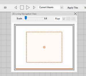
Use the options 2D and 3D in the Live toolbar to change the views. The highlighted area in the 2D navigation bar can be dragged around to change the view. The Living Wall module can also show a ‘fly around’; use the play keys.
Choose wheter you want to see alternatives presented based on favorites, tilsets or series. Or choose no change, to see the currently chosen tiling.
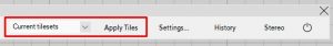
If you want to use the currently shown alternative in your project, use the function apply tiles to change the tiling in the project.
In Settings set the waiting time and type screensaver.
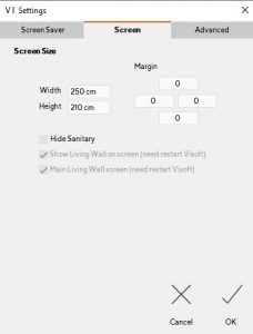
Use the tab screen to set the screen size of the monitor. this is really important for an accurate display. Use advanced for settings of the LivingWall if you have one.
The stereo option shows the design in 3D stereo. You need a suitable monitor, 3D tv or 3D glasses. Right click on stereo to set the stereoscopic settings.
When working in ViSoft, press F1 to open the manual. Here you read more about the functions of the living wall display.
Set after installing the projectors, the projection to 4:3.
Adjust in Windows the Display settings to:
- Multiple displays, select extend displays. Apply.
- Select identify, and choose the order.
- Select Standing and apply.
- Click on advanced monitordisplay.
- Set for both projectors the resolution to 1200×1600
(so the ratio is 3:4)
- Set for both projectors the resolution to 1200×1600
- Select identify, and choose the order.
Start ViSoft Premium
Press F8 to start the Live module for the first time. Open the settings and the tab Wall Board and press auto detect.
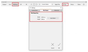
Project a wall board and check if the tiles are 1:1.
With the wallboard function, you can create and design show panels for your tiles in the showroom.
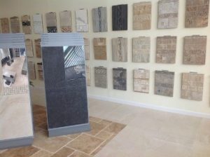
Collect in the tile browser the tiles you want to use, create a tileset or make them your favorite.
Go to Tile | Fast and open the  Wall Board Assistant.
Enable the Fixed size and set the parameters for width and height. In the ViSoft Preferences you can set a default size for the fixed size.

Drag and drop the tiles to the empty panel from the tileset or database.

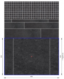
For the sections, you can control the rows, the height, the width. You can also set the way of laying tiles and the size and color of the joints.
Use the button Concept Board (top right)  to place the board in your project room. You can also choose to save the board. Use the button save…
Fill in the name and description and press ok. The concept board is saved in your Room object library (accessible in menu mural).
It is also possible to use tile with board function to place the board as a tiling area on the wall or floor.
With the grouping function, you can select multiple boards and save them in the mural library.
In menu Output |Plan you can see the exact amount of tiles needed for the board design.
Open the layers menu by clicking the button Drawing layers in the lower taskbar. Depending on the menu (tile, sanitary, output…), you can (dis)enable layers for the working area.


Parallel Projection
Parallel projection enables you to further customize the appearance of 2D-view. Reflection and shadows can be shown too.
Clipping distance
With this function, you can define the depth of the projection plane. This means you decide up to which distance to the selected wall or mural objects will be shown. Standard setting is Auto which means ViSoft automatically calculates which objects are visible. If you want to make further away objects visible, deactivate the auto function and enter the distance. The bigger the distance the more objects you see. Settings for the clipping distance have to be set individually for every plan.


You may have to load a tile image that has a (white) background, for example, a hexagon tile. Before loading it in ViSoft, you will have to make the background transparent. This can be easily done with Photofiltre (install for free). Open the image in Photofiltre. Select Image > Transparent color…
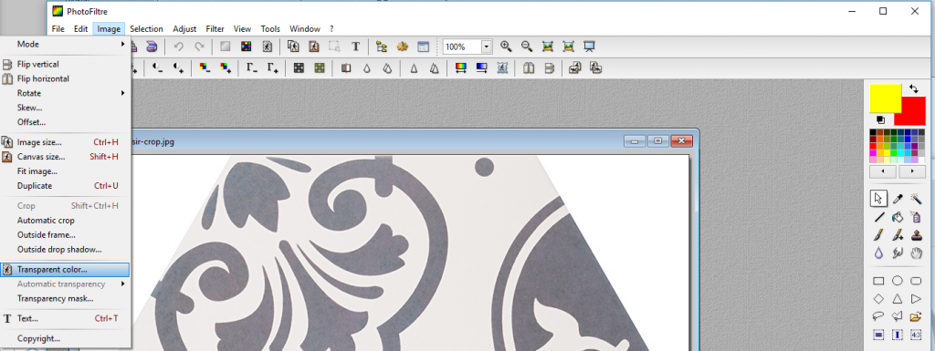
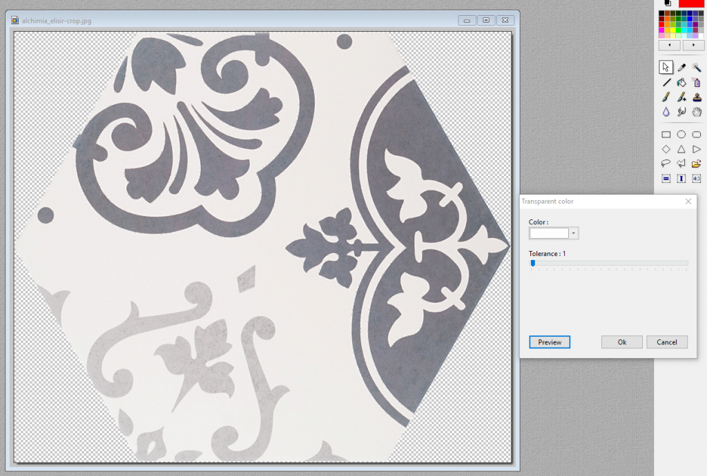
Select the background color. In this example the tolerance is set on 1, so no white color from the tile itself is lost. Press preview to check the result. If the result is good, press OK. Save the image in .PNG (* .png) (to keep the transparent background).
Open the Tile browser in ViSoft. Select .Custom Tiles and the serie – Rightclick and select Add Tile. Load the saved image and set the parameters.

The tile is saved in your database. Select the tile preview and press OK to use it.
To make a module of the hexagon tile, go to menu TILE | PLACE | TILES and press Module assistant (bottom menu).
In the Module assistant set the mode on Manual and open the element parameters under More…
Drag the tile image to the working space. TIP: Rightclick while dragging to rotate the tile.

Drag two more tiles and connect them. To get the right angle, use the Element parameters | Free angle. Set the joint size on 2/3 mm. Use the red arrow (drag with yellow circle) to connect the module. In this example, red areas appear to signal overlap. This is not an issue, however. TIP: Use the preview (bottom left), to check the end result and correct if needed.
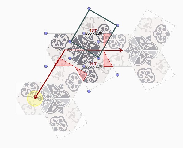 |
 |
 |
|---|---|---|
| Example module | Module is nicely connected | wrongly connected module |
Save the module as a tile pattern for future use (press save button upper menu). The tile pattern can be found under the tab Patterns in the tile browser.
Press OK to use the pattern in your project.
Import or export custom series
To import or export your custom made serie to other computers, right-click and select import or export to file. A .til format is created.

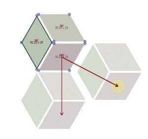
In the menu Tile | Place | Tiles press the module-assistant button to create your own tile patterns. If you want to know more about patterns with non-rectangular tiles, read more here.

Select the tiles you want to use and drag & drop them to the right. While dragging, use the right mouse button to turn the tile. Use more… to see more parameters. Use Free angle to get the exact angle.

Connect the arrow points by dragging the yellow circle. The preview (bottom-left) you can use to see if the laying of the pattern is correct.
Wild bracing different sized tiles
Open the module-assistant to create a wild bracing pattern. Drag and drop the tiles while holding shift. Multiple connection points appear. Save your created patterns with the save button. Under the tab Patterns in the tile browser you can use them again.

Example Roman tile pattern
Make a tileset in advance so that you don’t have to look up all tiles separately.

Load the tileset (select the serie in the database). Drag and drop the tiles, use right-click while dragging to rotate. If you have trouble snapping, switch to manual mode. Connect the tiling areas again.
Save the tile pattern
Save the tile pattern with the save symbol in the upper toolbar (within module assistent). If you want to use the tile patterns on other computers, copy (and paste to) from the following path C:\ViSoftCreative\Tiles\Patterns\ZZ_Eigen\.
Use a block mural to place a built-in bath with a panel beneath (and light).

Place a built-in bathtub and use the sanitary mural function to finish the built-in. Or do it yourself: place a block mural and use the Cut Out Filling function.
Set the mounting height of the bath at 15 cm, so there is empty space underneath the mural.


Use wall view to place and edit a new block (menu Room | Mural). Select all the objects and make it a group (CTRL+G). Now you can tile the mural, place a light, e.g.
 In the menu Output | Plan you find all the elevation pages of the room. Elevation pages are created automatically – one page for each wall.
The view in the elevation pages can be changed by moving the blue line in the navigation panel. It is also possible to remove or split the elevation with a right click.
You can add your own elevation with the button Create Elevation Page. Depending on how you draw the line the view will be above or below the line.
Right to left: Above the line.
Left to right: Below the line
Top to bottom: Right side
Bottom to top: Left side
Hit enter when you’re done or right click and select done or cancel.
A new Elevation page is created. You can rename the page by right clicking on the page name and select rename.
It is possible to add your own Impacts to the library. You need two images for ViSoft to work with. The first image has to be a JPEG in the correct size ( 128×128 pixels) the second the same image in png ( 24 x 24 pixels ). The images have to be placed in the following path.
Sanitary impacts in:
C:\ViSoftCreative\ Data \ Impacts\ Electrical
For ViSoft without dongle:
C:\ Program Files \ ViSoft \ ViSoftPremium\Data\ Impacts \ Electrical
The following Impacts are available for download here.
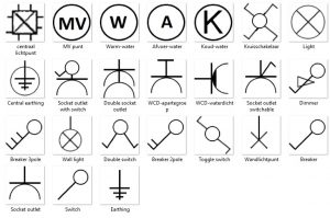
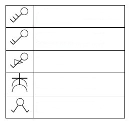
There are different possibilities to add a legend to the plans of your project. In the Output | Plan menu you can add a text label with the explanation and symbols as examples.
You can also create a legend in a program such as Word or Excell. if you then take a screenshot of that legend, you can add it as an image to your plan.
If you are missing symbols you can add them yourself in;
C:\ViSoftCreative\ UserData\Output\Symbols\
Online installation (without dongle) C:\ProgramData\ViSoft\ViSoftPremium\
Sanitary impacts are in:
C:\ViSoftCreative\ Data \ Impacts\ Electrical
Online installation:
C:\ Program Files \ ViSoft \ ViSoftPremium\Data\ Impacts \ Electrical
You can use the following image to create a legend of your own.
Fast consulting mode is perfect when you are advising customers and don’t want to see all the menus and functions. You work from the side browser only. Start this mode with CTRL + F11 and exit with Escape.
You can adjust settings for the side browser in the ViSoft preferences. Set shortcuts and choose which menus you want to work with.

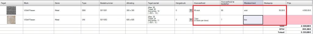
With this function, ViSoft calculates the number of boxes needed for the room. The price will then be shown in the part list of the Output.
For a correct price calculation, you will need to enter the price per box in the properties of the tile. You can find it in the: more parameters.

After the information is filled in, you can set the unit in the part list to box. The amount shows how many boxes you need and how many tiles are in the box. Next to the amount is the amount of boxes to order.
The price is calculated after the price per box, piece or m² is put in.
This function automatically calculates how many cut tiles can be reused in the project. It also shows ways how to cut the tiles for reuse.
To determine the reuse of tiles, turn on Tile offcut reusage layer. The tiles that are cut in half, are marked with the same color and index number (bold = the larger part, italics for the smaller cut).

In menu Output | Part list you open the part list for tiles. The calculations for tile optimization are shown here. Click on the question mark under reused tiles to open the Tile Offcuts window. Choose the way tiles can be reused, this depends on the structure.

 |
The texture of decorative tiles can’t be reused. |
 |
The tile texture can only be rotated horizontally or vertically.
|
 |
The tile structure can be rotated both horizontally and vertically. The tile can be reused and vice versa (tiles with the same repetitive texture in all directions) |

This window shows the tile cut plan. The black indicates the cutting loss.
In menu Output | Part list | Tile click on the Options… button to (dis)enable the calculations tile reuse automatically.
Open the Objects library in menu Room | Mural. In the ViSoft set are a couple of stairs you could use in your project. Another option would be to draw it with block murals. Or download and import a staircase from 3Dwarehouse for example.
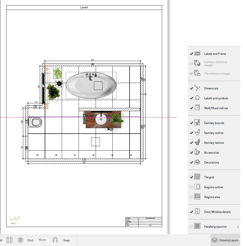
You can change the appearance of your Output plans by selecting what you want to see in the Drawing Layers.
In the Drawing Layers, You can turn on or off labels, wall/mural indices, sanitary bounds, etc.
In the drawing styles, you can change certain properties to change the style of your plan.
If you want to create your own base board, import or copy the tile to the .custom tiles database in the tile browser. The properties of tiles from manufactures are locked but can be edited if copied and paste in the custom database.
Browse through the 3D profiles and select one.

In menu Tile you can place the skirting board with the help of Wall Board Assistant. Press the button and start a new board. Drag and drop the skirting tile. If you want you can fill the whole board with tiles or you can add material to the wall.

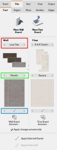
In Menu Tile | Fast you can use the wall- and floorboard assistant for automatic, quick and complete tiling. The boards are created with tilesets. Boards contain one or more tile areas.

Submenu Fast is divided into two sections: Wall and Floor. This enables you to select different tilesets for wall and floor.
Below the series name, you can see in the preview how the board will be placed on the wall or floor. Use the checkmark to place them in your project, unless Apply changes automatically is enabled. You can use < and > to browse through the auto boards. To select a different tileset click on the preview of the tiles. As you will see in the tiles browser some series have tilesets with both wall and floor tiles while others have no tilesets at all. If there is more then one tileset in the selected series you can change between them by clicking button < and > under the tileset. If the tileset contains floor tiles you can choose it as floor tileset with > and < between both tilesets.
Open the wall or floor board assistent to create your own boards.
Bord assistant
Click on the New icon. Open a tileset of browse to tiles you want to use. Drag and drop them on the board.
When you dropped a tile, an area is created. This you can easily edit with the options on the right side. Change the tile starting point, add joint colors, change the number of tile rows, add material, etc. You can also drag and drop the areas to change the order.

Save the board if you want to use it in future projects. The saved boards are accessible under the tab boards and you have to select the brand of the tiles you used in the database.
It can be useful to make tilesets for quick tiling in a project if you use the module-assistant or board-assistant. A tileset usually contains one or more basic tiles, decorations and borders, for walls, the floor, or both.
Some manufacturers included tilesets. If a series doesn’t contain any tilesets, the name is shown in a light grey color in the database. Tilesets are also being used to create auto boards (see Wallboardassistent).
Create tilesets
Open the Tile Browser. Open a serie and select a tile. Right-click and select Create tileset.

A window appears, fill in the data.

Add the other tiles in a similar way > open context menu and select add tile to tileset. You can select all the tiles with CTRL and add them all at once.
Browse to the tab Tilesets. Notice that all tiles are automatically sorted on type.
After sharing a panorama on the visoft360 platform (read here how to upload on ViSoft360), it’s possible to embed it on your website.
Go to the webpage of the panorama, open the tab Share it and copy the HTML code under embed.

If you use WordPress, use the code below with the ID of your panorama:
<iframe width=”1000″ height=”600″ src=”https://www.visoft360.com/Panorama/Embed/5660″ frameborder=”0″ allowfullscreen></iframe>
In submenu Door\Win you will find the functions to make (free) hollows and holes in murals and walls. A hollow can’t be placed on a free mural. Use a wall, divider or block. A hollow has a rectangular shape by default, choose free hollow to draw a different shape.
When you use a free mural to create a diagonal or round ending, combine it with a divider or block in the middle. That way you will be able to place a hollow on the straight part without any problem.

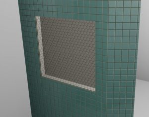
Free hollow
Free hollows and holes are created by placing nodes. Place nodes by clicking the left mouse button. After placing a node a line will be drawn from it in the direction of mouse movement. Lines drawn in such way must not cross each other.
If you placed a node by mistake you can undo it by clicking the right mouse button > delete last side or by pressing ESC key. By pressing SHIFT key you can select lines in a certain direction. You can also enter the length of the line in centimetres. If you press CTRL key the current line will be transformed into an arc. To finalize the free hollow or hole return to the first node or double click the left mouse button. Click Edit button on the lower task toolbar or double click the selected aperture to edit it. You can adjust the position of each node, add or remove nodes, turn the lines to curves or arcs and define segmentation.
In menu View| Material you can easily edit the materials of walls, murals, objects and other surfaces. Select the surface or object you want to change. A preview appears in the right menu. Open the Material library to select and place material. It’s also a possibility to import custom material based on an image, use for example textures from Vismats. Use the tabs simple and advanced to add or change bumpmaps and reflection etc.
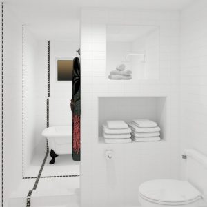
In this article is explained how to build in straight and round bathtubs, using the sanitary mural function or doing it manually using murals.
Built-in bath using the sanitary mural function
Manually build-in bath with block
Built-in round shaped bath using the sanitary mural function
Round freestanding bath built in a block
NOTE THAT: Not all baths are placed correctly with the sanitary mural function, depending on the 3D model. It can happen that there is a small gap between the bath and wall, causing errors in the tiling plan (tiles will be placed in the gap). Check in Wall-view if the mural of the bath is placed against the wall, it will be shaded in grey. If not, you will have to draw a mural manually. See under second heading.

Placing a built-in bath with the sanitary mural function
Choose the bath you want to build-in in the sanitary browser. Adjust the mural height and size where necessary, so that the bath fits nicely.

Press Ok to place the mural. You can double-click to move the bath. If you wish to edit the mural freely, you need to ungroup the mural and bath. The free construction options will then be available.

Manually build-in bath with block
First, place the bath in the room. Go to menu Room | Mural to place a block.

Doubleclick on the block, use the white rectangles to drag the block to the correct size. Set the height of the mural a couple of centimetres lower as the height of the bath.

Go back to menu Sani and press the button Cut out filling to remove the mural inside the bath. The mural is ready to be tiled now!

Built-in round bath using the sanitary mural function
Open the sanitary browser and place a round-shaped bath. Press the sanitary mural in menu Sani. Choose for a smooth shape. Pay the attention to segment length, this is important for the tiling.

Go to menu Tile | Place | Tiles and select tile you want to use. Go to mural view and use the button mural faces to place the tiles on the bath mural. In the image below you can see the tiling is a bit off.

To solve this, add or delete segmentation points. Go to menu Room | Mural. Open the explorer on the left side. Ungroup the bath and mural. Go to floor sight and double-click on the mural to open the free construction options. Now you can add or remove segmentation nodes. Select a node to remove, or select a line to add a node.

Round freestanding bath built in a block
Place a round bath, in the example below a bath from the Vitra – Istanbul serie is used.

Place a block until the centre of the bath.

Right click on the block and select convert into free mural.

Select the button line. Add two nodes en place them on the outer bath frame.

Select the line between the two nodes. Click on to arc. Drag the arc in the opposite direction, until it flips inwards. 
Place the arc against the bath frame.

The mural can be tiled.

Use murals to make your own customized sanitary objects, like marble fontains, built-in baths or sinks. First, place the sanitary object. Second, place a free mural. Set the height of the mural a couple of centimetres lower as the sanitary object. It is possible to edit the mural to make an arc e.g.
If you wish to create a built-in bath, read this article. In this article, you can read how to create a custom undercounter basin or a washbasin built created with murals.
Under counter washbasin (undermount)
Place a block in the room (menu Room | Mural). Set the properties, for example, width 80 cm, thickness 60cm, height 3cm. Set the mounting height to 83 cm.

Go to menu Sani and place an under counter basin. In the example one is used of the series O.novo / Villeroy & Boch. Use floor and wall-view to center the bashin precisely on the mural. The tools ![]() in the bottom toolbar are very useful for this.
in the bottom toolbar are very useful for this.

Use the tool Cut out filling in menu Sani. The under counter washbasin assistant opens. If needed, edit the margin cut. Press OK.

Finish the basin, add tiling or material and other sanitary objects.

Custom washbasin
You can create a custom washbasin, using only murals. Go to menu Room | Mural and press Free divider. Make sure snap is on and put your grid on 5 cm (lower toolbar). Start drawing. Set the path construction options to thickness 5 cm and direction left.

When you connected the endpoint to start point, right click and select End drawing. Set the height under properties at 6 cm.
Select free mural and draw a rectangle inside. Set the properties at 2 cm.

Go to mural-view. Select free again, and draw a corner like in the picture below. Go to floor-view to set the width properties correctly.

Murals are automaticly tiled when using auto-bords or the all walls button. To avoid this, draw a region over all the mural areas (menu Tile | Region). Use mural-view and the navigation board to select the areas.
Place material on the surface. Open the material library in menu Tile |Place |Material and select ceramic or custom material e.g. Hold CTRL to paint the material on the surface. If you want to save your custom washbasin, group the murals. Drag a rectangle and select Group from the context menu.

Open the context menu again, and select save to Library. Save the object to your custom mural library, or use export to file…to save on your computer. Share it with other ViSoft users and import the object in .custom object in the sanitary browser.

Sanitary can be mirrored on the X-axis or Y-axis, in 2D- or 3D-view. Right-click on an object and click Mirror > X or Y.

To change the Page setup to landscape, go to Output | Plan and open Print Settings.
Select Printer Setup > Properties and change the Orientation.
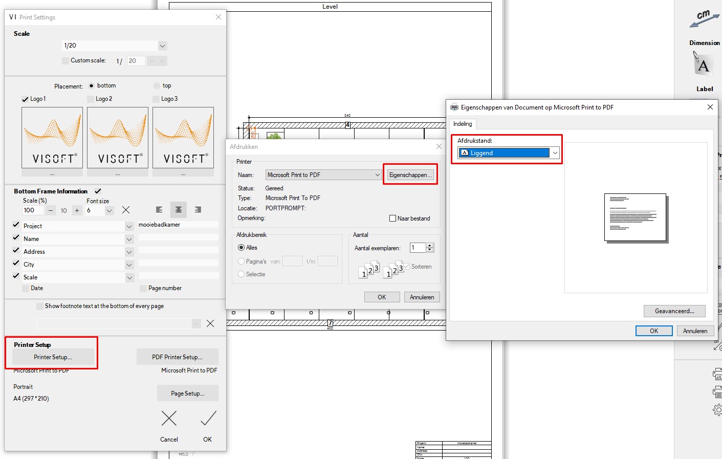
In menu Output| Plan select Print settings…(lowest button right menu)
Under scale select custom scale and enter the scale you want to use.
In ViSoft you can adjust the object however you like. It is not possible to modify an object in the database of the manufacturer (protected), but you CAN copy the object to .custom objects and make changes to the object or tile there.
Copy the object you would like to change, and paste it in .custom objects serie. Rightclick and select Properties. Edit the order number to avoid a wrong order. Open the tab Geometry and click Edit parts. Select a part you like to edit in size or to delete. Check that the lock is disabled.

Object parts browser
Open the Object parts browser to get an overview of all the parts (button left of object preview). You can select multiple parts by selecting and pressing CTRL. Use the Highlight selection button to see which parts are selected. The other parts are shown in wireframe.
To edit the material, open the material tab. Select a part you wish to edit the material of, and browse through the templates.


It is possible to add light to a certain part of the object. Open the light tab and add a point or spotlight. You can set all the properties for the light as well.
While placing a dimension in Menu Uitgave | Plan, hold SHIFT to draw a diagonal dimension.

This article shows two examples to explain how border tiles are laid in ViSoft. Tiles of the manufacturer Original style are used. You can download the Original style database in the update manager.
Example one tile border

Step 1
Open the tile browser in menu Tile. In the example tiles 8021V, 8022V, and 8023V from the Odyssey series from Original Style are used. Create a tileset with a right click> Create tileset. Place tile 8021V on the floor, set the tile orientation to ‘quad'(ratic).

Step 2
Open menu Tile | Region. Draw a region, the size of a bathtub for example. After drawing you can set the exact properties.

Step 3
Go to menu Tile | Borders. Select tile 8023V under border tile. Click on button Region and click on the floor area. The border is placed. Doubleclick on the border for free construction options. Drag the white points to move the border.
Example two: multiple tile borders

Step 1
Start a new project and select an L-shaped room from the quick wizard. Go to menu Tile in the tile browser. Select the following tiles (hold CTRL) from the Original Style database from serie Victorian floor tiles: 7104v, 7504v, 7704v, 7706v, 7121v, 7518v, 7639v and 7725v. Right-click and select Create tileset. Fill in the data. Open the tab Module assistant in the tile browser.
Step 2
First, we create a base pattern. Open the tileset and drag tile 7104V twice and 7704V and 7504V once to create a square. Check the preview and press OK. Place the pattern on the floor and turn the tiling angle 45 degrees.

Step 3
Go to menu Tile | Borders. This step explains how to set the first border and to create a neat cutting plan for the base pattern.
Go to floor view and open menu Tile | Borders. Select border tile 7121v. Click on the button Free to draw a region over the centre of the tiles. Make sure snap to tile centre is on. After placing the border, set the orientation to the right (the border is placed outside the base region). Draw a free region against the inner outline of the border. Delete the base pattern and place it again inside the border. The outer region is now free of tiling.

Step 4
Open the module-assistant to set the next border. Rightclick on the button Module under way of laying tiles. Press New to start a new module.
Drag tiles 7518V (triangle) and 7639v(diamond) to the blank space. TIP: While dragging, right-click to rotate the tile. To get the diamond in the proper angle, open More… to use the parameter Free angle. Connect the tiles horizontally. Press OK. Click on Region to place the strip.

Step 5
Set the border tile 7121V again. Select Region and place on the floor.
Select tile 7725V. Repeat steps to place.
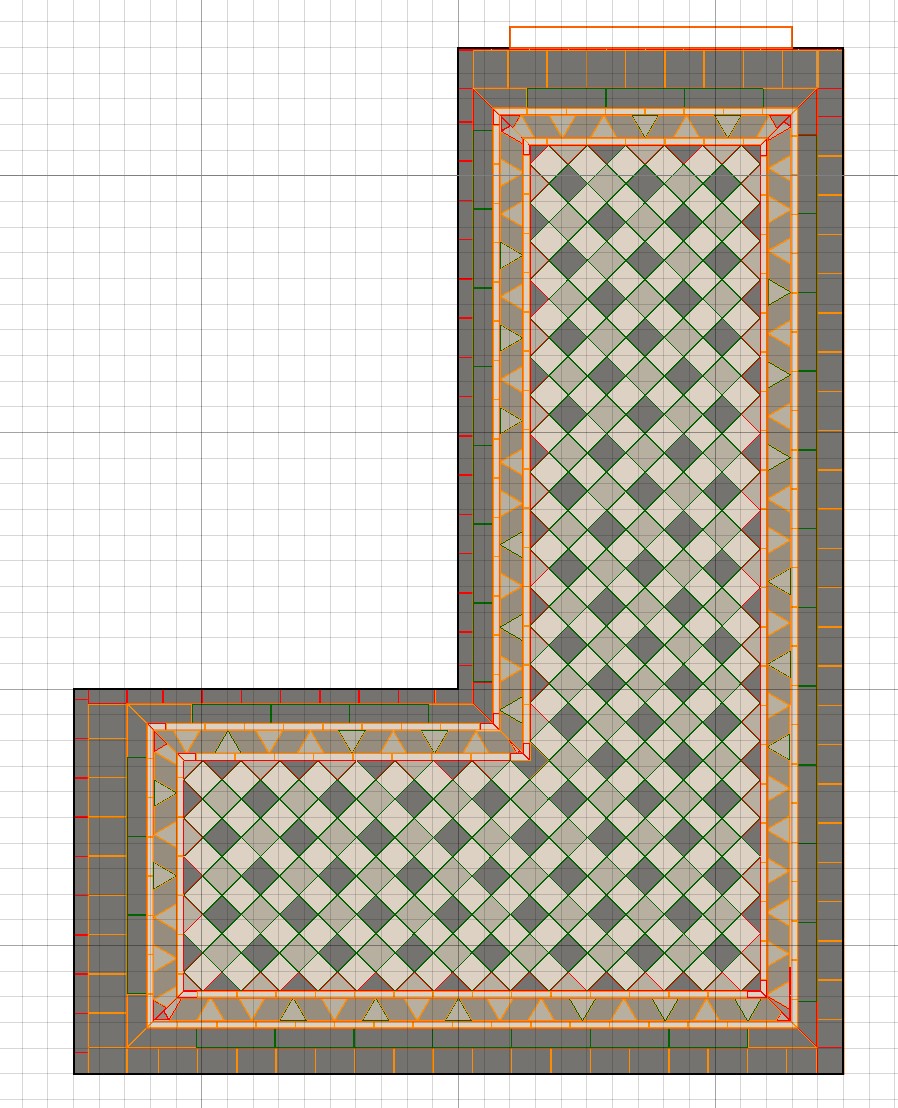
To finish the floor tiling, set base tile 7706V in menu Tile | Place | Tile and place in the outer area. Select the right tile position and joint setting for a nice tiling cut.
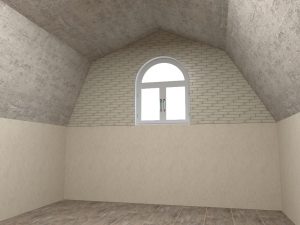
Draw a mansard roof or similar roof using a free mural.
Step 1
Set up the room. Select the wall where you want to place the mural in the navigation panel, and switch to wall view.
Step 2
Select in menu Room | Mural the free mural function. Draw a closing triangle. Doubleclick on the triangle to start free construction options.
Step 3
Select the diagonal line and click on the insert button (plus sign). A white bullet appears, drag it to the desired position. The other option could be to change the diagonal line to an arc or curve. Press enter to stop editing.

Step 4
Select de mural and copy – paste it. Rightclick to open the context menu and select mirror > X. Put the mural in the right corner.
Step 5
Go to floor view. Select the mural and set the thickness to the same dimension of the length of the wall.
It is possible to create a skylight. The ceiling of a room is automatically created in ViSoft premium and not editable…but you can turn it off and on in the navigation panel (in 3D view).
Create a new ‘ceiling’ by placing a mural with a mounting height set on the height of the walls (for example 250cm). Turn off the ceiling in the navigation panel.

In 3D-view you can see the new ceiling. Switch to floor view and create a hole (menu Room | Door/Win).
Hold Shift for extra guidelines, CTRL for round lines. To create a circle, make two short straight lines, as done in the example below.
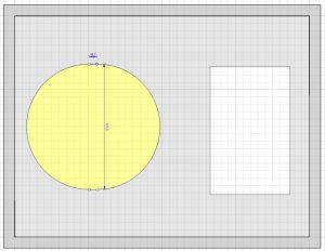
The result in 3D-view.
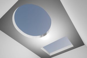
To draw round Walls make sure you are in the Menu Room | Wall.
While drawing, keep CTRL pressed to create an arc.
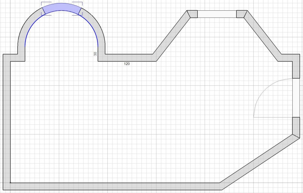
You can change the radius after placing the arc. Select the round wall, and move the little orange circle upwards or downwards to switch the direction of the rounding.

Creating round murals
To draw a round mural use the free (divider) mural in the menu Room | Mural.
First, you draw the free mural in the desired shape. 
Doubleclick on the mural to open the free construction functions. Select the line to form it to a curve or arc. Select the small green circle to change the radius. 
Repeat the steps on the other lines to create a rounding.

Take note: Hallows can’t be placed on round and free murals. On the straight part of the free divider mural, it is possible to place a hallow.
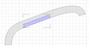
If the tiling doesn’t look good on the round part of the mural, you can create extra segmentation points. Doubleclick and add the desired number of points.

To use the Quick room wizard, go to menu Room | Wall, and press the button Quick room. Here you can choose a predefined room shape, saving you time from drawing the walls manually.

Define the length of each wall, click and type, use TAB to spring to the next field. Use the buttons to rotate or flip the room if desired. Press OK when finished. Note that afterwards the lengths of walls can be edited, but not the shape. Edit the wall properties in menu Room | Wall.
You can choose to draw the project room manually. In ViSoft there is a distinction between walls and murals. Walls form the shell of the project: always the outer edge. Walls form the partition of the room.

Go to menu Room | Wall to begin drawing the walls. The cursor changes in a green cross. Drag the wall to an endpoint or type in the length and press enter.
TIP: always draw clockwise, so the inner and outer walls are facing the right way. If not, it causes troubles when placing tiles and roofs.
Set the angle mode to automatically draw corners in 90 degrees or free. Or keep SHIFT pressed to change modes.
To draw Round walls keep CTRL pressed.
There is no need to draw the last wall: use the button Close room. If you prefer to close it, take note the last point meets the first point to close the room correctly.
Select a wall to move it. Connecting walls are automatically adjusted to the change. This function also works after placing tiling and sanitary.
Walls can be divided. Select in floor view a wall, and select with a right mouse click Split.
 A room can be mirrored or flipped at any time. To flip the project space, go to menu Room | Wall and press flip room vertically or flip room horizontally.
Take note when flipping the room, the placed objects keep their original order number. Most sanitary objects are symmetrical and can be flipped without problems. But pay attention to shower wands etc.
Set the preference to (dis)enable that products are mirrored while flipping a room. Go to File > Preferences > Defaults > Sanitary.
In the Parts lists mirrored sanitary objects are coloured red, so you can take note.

Trace a project based on a background image or CAD file.
Step 1
Start a new project in ViSoft Premium.
Step 2
Right-mouse click in the working area > select Background image > Load > Image file or CAD file.

Step 3
Select and open the file.
Step 4
Set the scale factor for the image, select scale factor from the context menu.
Step 5
Select two point of which the distance is known and put in the measurement.
Step 6
Place the walls, murals, doors and windows and enter the correct dimensions.
Step 7
When you are done tracing, you can remove the background image. Rightclick to open the context menu and select background image > delete.
Go to slanted roof
Go to roof corner
Go to complex roof
Learn how to create roof corners, slanted and more complex rooms in ViSoft Premium.
Open the menu Room | Roof. Note that you can only place a roof in floor view, the function is not available in the other views. Click on roof and place it on the wall. The roof is highlighted: set the right parameters under properties. This you can do in 3D-view if you wish.

- Mountingheight: set the start point of the roof.
- Angle determines the angle of the slope.
- Depth of the selected roof.
2 | Roof Corner
To place a roof corner, use the function Roof Corner in menu Room | Roof and work from floor view. Select the corner where you want to place the roof. Fill in the right properties in 3D to see the changes you make.
To create a complex roof, with 2 corners or roof rafters, use extra block- or free murals. The following example uses the roof function, 2 blocks, 3 free murals and 1 divider.

Step 1
Start with placing the roof. Set the mounting height to 0 and angle to 70 under the properties.
Step 2
Place a block (tab mural in menu Roof) up against the roof. Open the properties, and set the bottom bevel angle (b) to – 40.
Step 3
Place the divider and block on the ground against the sloped roof. Set the right properties. Don’t worry about the back: it automatically shapes in the right form against the wall.
Step 4
The rafters you can create with a free mural. Go to wall view. Use the navigation panel to select the wall where you have a side view of the roof.
Draw the free mural against the block in the right shape. Connect the start with the endpoint and edit the properties if needed. For multiplying the rafters, simply use copy and paste.
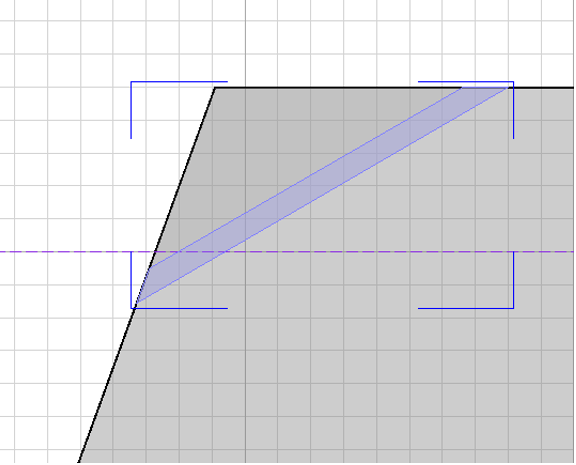
Free mural in wall-view.
In the menu Room | Door/Win left-click on the door or window button to place one in your project. The cursor turns into a door sign, click on the desired spot on the wall to place the aperture.

To customize the look of the doors and windows, right-click on the door or window button or use the Door/window Assistant button below in the menu.

In the Door/Assistant menu, you can set the appearance of the selected aperture. In the top left corner of the menu, the folders Custom, Doors and Windows are located. All three folders can be expanded.
To the right of the folders, you can see different types of apertures from the selected folder. Click on one of them. Preview of selected door/windows is visible in the left lower corner of the screen. On the right side of the menu, there are different tabs with for setting aperture properties.
To use the same texture on all elements of your currently selected door or window click button Common material in Window / Door tab and select the texture you need.
For DOORS you can enable the hinges, the sill, the door leaf. Customize the material, the handle, and add sight windows when desired.
For WINDOWS browse through the tabs Window, Window Casing, Filling, Frame, Handle to customize your window.

You can save custom created doors and windows by using button Save to Library (button in the middle, below door previews).
Click Apply Style to all button to use same settings on all previously place windows/doors in your project.
If you want to change the appearance of already placed doors and windows select one of them, then click button Door/Window Assistant again.
To edit the properties of the aperture, use the parameters in the menu. Pay attention to the depth of the aperture, if the reveal is going to be tiled.
Apertures can be automatically centred or placed very exactly. Doubleclick on the aperture in floor view or wall view. Click on the numbers and type the exact distance. In the lower taskbar, you can make use of the centre function buttons.

Doors and windows can be opened and closed in 3D-view. Ideal for checking the turning circle. The mouse changes in a hand with red turning arrows. Keep the right-mouse button pressed and move to left or right to change the degrees.
ViSoft is a open software, which means you can create all the objects and textures you desire. It’s possible to import any object of the following file formats:
-
- Autodesk 3Dstudio (*.3ds)
- WaveFront Object (*.obj)
- Collada (*.dae, *.xml, *.zip)
- DirectX (*.x)
- Blitz3D (*.b3d)
- WRML97 (*.wrl; *.wrz)
- *.dwg
Use drag & drop to import objects and textures; its very easy to drag the downloaded file from the internetbrowser to ViSoft Premium. The object is loaded en can be placed in the room or added to your own library.
.Custom Objects library
In the sanitary browser you can add your serie with custom objects. Rightclick on .Custom tiles (or objects) and select Add Series. Fill in the name and description of the new serie. It’s also possible to import and export series from the .custom database to other ViSoft installations.

Objects and tiles in the custom database can be modified. Read more on how to edit objects or tiles.
The websites below provide interesting objects and textures for downloads:
(Click on the logo to visit site)
| Interior blog, provides info on new design and lots of 3dfiles. | Free | |
| Really extensive library, which is also integrated in the ViSoft sanitary browser. | Free | |
Texture Haven |
High-quality textures, free to download. | Free |
HDRI Haven |
High-quality HDRI’s, free for download | Free |
|
Lots of architectural products, as well as furniture and lighting. | Free |
|
Mostly architectural objects but textures as well. | Free |
| baths, armature, sinks | Free | |
|
Design interior | Free |
|
A wide range of 3D objects | Free |
| A wide range of 3D objects | $ 49,95 per year | |
| Materials and 3D-objects | Free | |
3DTEXTURES |
Textures | Free |
If you want to use combinations of objects in the future, you can save them in the library. First, you have to group the objects. Select all the articles in wall-view, holding CTRL or drag a rectangle over all the articles. Right-click and select Grouping > Group (or use hotkey CTRL + G).

The objects are grouped. Right-click again and select Save to library… or save to custom database…(object will be saved directly in .custom objects > default. You will have to edit the properties in the sanitary browser).

Save to library saves the group in the objects (mural) library. You can make new folders and save groups of objects. If you prefer to save a file on your hard disc or in the sanitary browser, use Export to file… You can import the group in the sanitary browser under .custom objects or even use the file in other software.
The function ‘Image board’ shows 2D images as 3D objects. You will need an image (png) with a transparent background.
Step 1
Look for a PNG image file with transparant background to use as image board.

Step 2
Go to Menu Sani | Sanitary and press the button Image bord.
Step 3
Go to .custom materials in the Material library. If you want to make a new folder, open context menu on .custom materials and select add series.
Stap 4
Add the image > Select add material from image (right click in white folder space). Fill in the details under Material Properties if you like.
Step 5
Place the image board in the room. If you want to make adjustments, use the properties in the left menu.

To add your own tiles, open the tile browser (menu Tile | Place | Tiles).
In the left menu of the tile browser, the database tree, you select .Custom Tiles. Rightclick and select Add Series.
Give a name and description and select OK.

Rightclick (whitespace) and select Add Tile and load the tile picture. In the Tile Properties window insert the description, order number, type of tile, etc.

Press OK and start tiling!
Adding a non-rectangular tile
You may have to load a tile image that has a (white) background, for example, a hexagon tile. Before loading it in ViSoft, you will have to make the background transparent. This can be easily done with Photofiltre (install for free). Open the image in Photofiltre. Select Image > Transparent color…
Select the white color. In this example the tolerance is set on 1, so no white from the tile itself is lost. Press preview to check the result. If the result is good, press OK. Save the image in .PNG (* .png) (to keep the transparent background).
Open the Tile browser in ViSoft. Select .Custom Tiles and the serie – Rightclick and select Add Tile. Load the saved image and set the parameters.
The tile is saved in your database. Select the tile preview and press OK to use it.
To make a module of the hexagon tile, go to menu TILE | PLACE | TILES and press Module assistant (bottom menu).
In the Module assistant set the mode on Manual and open the element parameters under More…
Drag the tile image to the working space. TIP: Rightclick while dragging to rotate the tile.
Drag two more tiles and connect them. To get the right angle, use the Element parameters | Free angle. Set the joint size on 2/3 mm. Use the red arrow (drag with yellow circle) to connect the module. In this example, red areas appear to signal overlap. This is not an issue however. TIP: Use the preview (bottom left), to check the end result and correct if needed.
|
|
|
|---|---|---|
| Example module | Module is nicely connected | wrongly connected module |
Save the module as a tile pattern for future use (press save button upper menu). The tile pattern can be found under the tab Patterns in the tile browser.
Press OK to use the pattern in your project.
Import or export custom series
To import or export your custom made serie to other computers, right-click and select import or export to file. A .til format is created.
Everything you design in ViSoft is automatically converted into technical drawings and part lists in menu Output. There is a division between plans, part lists and picture print.
Output | Plan
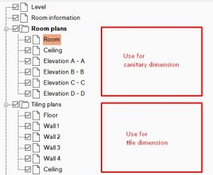
In de Explorer (left side screen) you can select the plans. Click to view.
Delete or add dimensions to the plans. Or include extra text, pictures, logos and custom pages.
ViSoft measures automatically the dimensions between placed objects. It’s easy to add extra custom dimensions.
Take note: the first plan level is for dimensions on the outer walls. The room plans can be used for dimension within the room.
Manual measurements
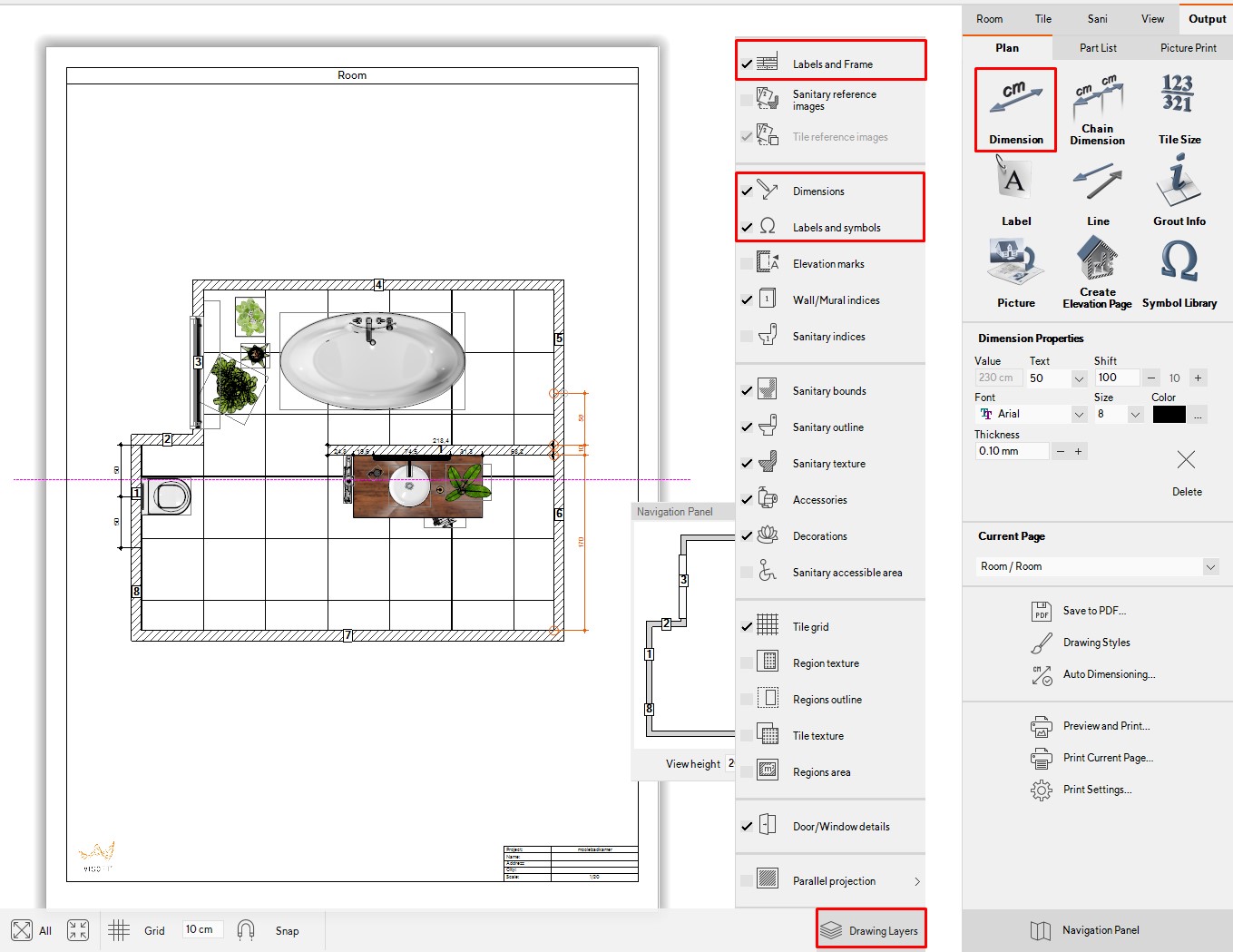
First of all, make sure that in the drawing layers the Labels and Frame, Dimensions, labels and symbols are checked.
Use the button Dimension to measure the distance between two points. Activate the button and click on the first point. Hold left mouse key and release on the second point. You can move the line by dragging it.
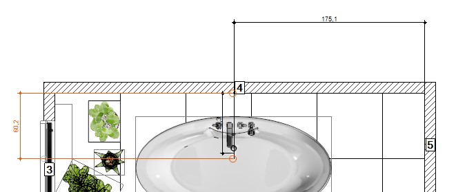
In the right menu under Dimension properties, you can change the look of the dimension, size, font, color e.g.
Adjust the design with the Drawing Styles layer. The changes you make here will be saved as default. If you like to keep the style for the whole company, copy the settings from the folder ViSoftCreative/ userdata / settings.xml to other ViSoft computers.

Chain dimension
Use the button Chain dimension if you want to measure multiple points. Left-click on the points, for example, the heart of objects. Stop the chain with enter or double-click.
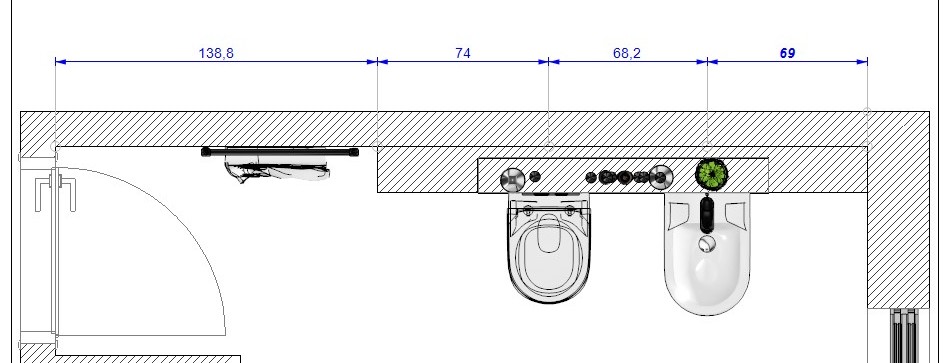
Auto dimensioning
It is possible to edit the settings for automatic dimensions. Click on the button Auto Dimensioning to open the table seen as below.
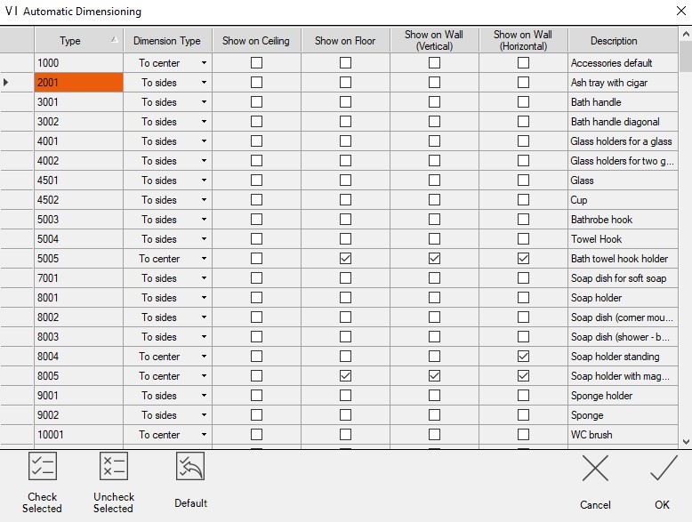
Each type of product is presented in a separate row. In the first column you see product codes. In the second column, select the dimension type: display in the middle or to the sides. In the third and fourth columns, you select whether the product type is displayed on the floor and ceiling plan. The fourth and fifth columns indicate if dimensions are shown on wall plans and elevations. Use CTRL or SHIFT to select multiple rows at the same time. Then use the button Check selected or Uncheck selected. Basic settings can be reset with the Default button.

In ViSoft it is possible to change the surrounding of the project to a cloudy sky, a photo, or even a 360-spherical image.
Go to menu View | Light | Sun and sky. Look under Sky properties to change the style of the background. Disable sky (same as inside lights). Use the dropdown menu from Sky to choose a sunny, cloudy or even a stormy sky.
It is also possible to import your own environment file to use as a background. Press the import button. Select the image, give it a name and select the type in the import window. Press OK. You can use the parameters to set the image, and use Align to view: the image will adjust automatically to the current viewpoint.
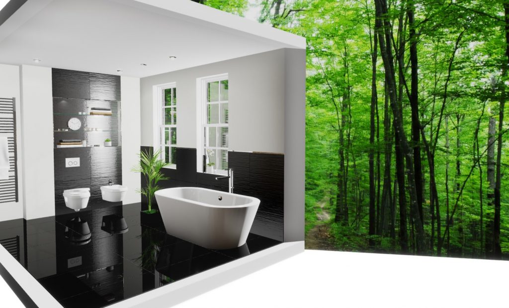
360 panorama
If you want to use a 360-photo, take care it has a high resolution (8k). The rotation, saturation and horizon height can be adjusted. These spherical images are suitable for apartments with a lot of windows, to create an extra wow-factor. Adding a 360-panorama goes the same as explained above, use import and select type spherical.
Suitable 360 images can be found when you use the search term “spherical panorama” Google images. Search for a high resolution, for example, larger than 4 MP. On Viz People you can download six ‘spherical Skies’ for free.

Change the viewpoint with one mouse-click in menu View | Camera.
Use the explorer (viewpoints) in the left-browser (binoculars), or change the viewpoint using the buttons in the right menu. Top, back, left, center, right and front are all automatic viewpoints. In the explorer, you will find some more automatic viewpoints as best corner, from the smallest wall…
Change the view easily with the cursor keys ←→ to rotate and ↑↓ move back or forward. Or use WASD, + QE to move the view up and down.
Use the Properties parameters to change camera set up. You can also change the lens, to wide angle for example.
Enable curtains to see the viewpoint in the chosen image resolution. This makes it easy to check if all details are visible before you save or render the image. You can use turn on the grid to check the composition.
The function optimize perspective minimizes any distortions of diagonal lines in the camera angle. Use this option when joints appear irregular or cut. This function is disabled for viewpoints with very oblique views.
The navigation panel is a helpful tool to see where the camera stands in the room. You can drag the circle which represents the camera, and rotate the field of vision. Use the navigation panel to save custom viewpoints. If you are satisfied with your current viewpoint, save it by clicking on one of the circles numbered 1 to 10.
Note: you don’t have to use the save button. Only if you want to rewrite an already saved viewpoint, use the save button.
